Lexus ES: Speed Sensor
Components
COMPONENTS
ILLUSTRATION
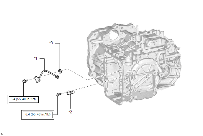
| *1 | TRANSMISSION REVOLUTION SENSOR (NC) | *2 | TRANSMISSION REVOLUTION SENSOR (NT) |
| *3 | SPACER | - | - |
.png) | Tightening torque for "Major areas involving basic vehicle performance such as moving/turning/stopping": N*m (kgf*cm, ft.*lbf) | - | - |
Installation
INSTALLATION
PROCEDURE
1. INSTALL TRANSMISSION REVOLUTION SENSOR (NC)
(a) Install the transmission revolution sensor (NC) and spacer to the counter drive gear sub-assembly with the bolt.
Torque:
5.4 N·m {55 kgf·cm, 48 in·lbf}
2. INSTALL TRANSMISSION REVOLUTION SENSOR (NT)
(a) Install the transmission revolution sensor (NT) to the automatic transaxle case sub-assembly with the bolt.
Torque:
5.4 N·m {55 kgf·cm, 48 in·lbf}
3. INSTALL TRANSMISSION VALVE BODY ASSEMBLY
Click here .gif)
Removal
REMOVAL
CAUTION / NOTICE / HINT
The necessary procedures (adjustment, calibration, initialization or registration) that must be performed after parts are removed and installed, or replaced during transmission revolution sensor (NT) and transmission revolution sensor (NC) removal/installation are shown below.
Necessary Procedures After Parts Removed/Installed/Replaced| Replaced Part or Performed Procedure | Necessary Procedure | Effect/Inoperative Function when Necessary Procedure not Performed | Link |
|---|---|---|---|
| Replacement of automatic transaxle fluid | ATF thermal degradation estimate reset | The value of the Data List item "ATF Thermal Degradation Estimate" is not estimated correctly | |
| Replacement of transmission valve body assembly |
|
| for Initialization: for Registration: |
PROCEDURE
1. REMOVE TRANSMISSION VALVE BODY ASSEMBLY
Click here .gif)
2. REMOVE TRANSMISSION REVOLUTION SENSOR (NT)
| (a) Remove the bolt and transmission revolution sensor (NT) from the automatic transaxle case sub-assembly. |
|
.png)
3. REMOVE TRANSMISSION REVOLUTION SENSOR (NC)
| (a) Remove the bolt, spacer and transmission revolution sensor (NC) from the counter drive gear sub-assembly. |
|
.png)
READ NEXT:
 Torque Converter And Drive Plate
InspectionINSPECTION PROCEDURE 1. INSPECT TORQUE CONVERTER ASSEMBLY (a) Inspect the one-way clutch. Press on the splines of the stator with a finger and rotate it. Check that it rotates smoothly when
Adjustment
ADJUSTMENT PROCEDURE 1. SECURE VEHICLE (a) Fully apply the parking brake and chock a wheel. CAUTION:
Make sure to apply the parking brake and chock a wheel before performing this procedure.
If th
SEE MORE:
Power Source Circuit
DESCRIPTION This circuit is the power source circuit for the stereo component equalizer assembly. WIRING DIAGRAM CAUTION / NOTICE / HINT NOTICE: Inspect the fuses and relays for circuits related to this system before performing the following procedure. PROCEDURE 1. CHECK HARNESS AND CONNECTOR
Multiplex Tilt And Telescopic Ecu
ComponentsCOMPONENTS ILLUSTRATION *1 LOWER STEERING COLUMN COVER SUB-ASSEMBLY *2 MULTIPLEX TILT AND TELESCOPIC ECU RemovalREMOVAL PROCEDURE 1. CHANGE POWER TILT AND POWER TELESCOPIC STEERING COLUMN SYSTEM SETTINGS Click here 2. REMOVE LOWER STEERING COLUMN COVER SUB-ASSEMBLY Click
