Lexus ES: Sound Signal Circuit between Radio Receiver and Stereo Jack Adapter
DESCRIPTION
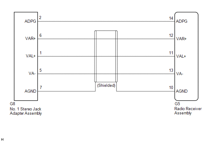
The No. 1 stereo jack adapter assembly sends the sound signal from an external device to the radio receiver assembly via this circuit.
WIRING DIAGRAM
PROCEDURE
| 1. | CHECK HARNESS AND CONNECTOR (RADIO RECEIVER ASSEMBLY - NO. 1 STEREO JACK ADAPTER ASSEMBLY) |
(a) Disconnect the G5 radio receiver assembly connector.
(b) Disconnect the G8 No. 1 stereo jack adapter assembly connector.
(c) Measure the resistance according to the value(s) in the table below.
Standard Resistance:
| Tester Connection | Condition | Specified Condition |
|---|---|---|
| G5-14 (ADPG) - G8-2 (ADPG) | Always | Below 1 Ω |
| G5-10 (AGND) - G8-7 (AGND) | Always | Below 1 Ω |
| G5-12 (VAR+) - G8-6 (VAR+) | Always | Below 1 Ω |
| G5-11 (VAL+) - G8-1 (VAL+) | Always | Below 1 Ω |
| G5-13 (VA-) - G8-5 (VA-) | Always | Below 1 Ω |
| G5-14 (ADPG) or G8-2 (ADPG) - Body ground | Always | 10 kΩ or higher |
| G5-10 (AGND) or G8-7 (AGND) - Body ground | Always | 10 kΩ or higher |
| G5-12 (VAR+) or G8-6 (VAR+) - Body ground | Always | 10 kΩ or higher |
| G5-11 (VAL+) or G8-1 (VAL+) - Body ground | Always | 10 kΩ or higher |
| G5-13 (VA-) or G8-5 (VA-) - Body ground | Always | 10 kΩ or higher |
| OK |  | PROCEED TO NEXT SUSPECTED AREA SHOWN IN PROBLEM SYMPTOMS TABLE |
.gif)
| NG | | REPAIR OR REPLACE HARNESS OR CONNECTOR |
READ NEXT:
 Start Up Signal Circuit between Radio Receiver Assembly and Navigation ECU
DESCRIPTION This circuit includes the navigation ECU and radio receiver assembly. WIRING DIAGRAM PROCEDURE 1. CHECK HARNESS AND CONNECTOR (RADIO RECEIVER ASSEMBLY - NAVIGATION ECU) (a) Disco
Steering Pad Switch Circuit
DESCRIPTION This circuit sends an operation signal from the steering pad switch assembly to the radio receiver assembly. If there is an open in the circuit, the navigation system cannot be operated us
Stereo Jack Adapter Light does not Illuminate
DESCRIPTION Power is supplied to the No. 1 stereo jack adapter assembly illumination from the radio receiver assembly. WIRING DIAGRAM CAUTION / NOTICE / HINT NOTICE:
Depending on the parts that ar
SEE MORE:
Components
COMPONENTS ILLUSTRATION *1 REAR DOOR FRONT WINDOW FRAME MOULDING *2 REAR DOOR WEATHERSTRIP *3 REAR DOOR WINDOW FRAME MOULDING SUB-ASSEMBLY *4 RIVET ● Non-reusable part - -
Check Bus 1 Lines for Short Circuit
DESCRIPTION There may be a short circuit between the CAN main bus lines and/or CAN branch lines when the resistance between terminals 23 (CA1H) and 8 (CA1L) of the central gateway ECU (network gateway ECU) is below 54 Ω. Symptom Trouble Area Resistance between terminals 23 (CA1H) and 8 (CA
