Lexus ES: Side Camera Current Malfunction (C1684)
DESCRIPTION
This DTC is stored if the parking assist ECU judges as a result of its self check that a synchronization problem is occurring in the image signal sent from the passenger side television camera assembly to the parking assist ECU.
| DTC No. | Detection Item | DTC Detection Condition | Trouble Area |
|---|---|---|---|
| C1684 | Side Camera Current Malfunction | Side camera current malfunction |
|
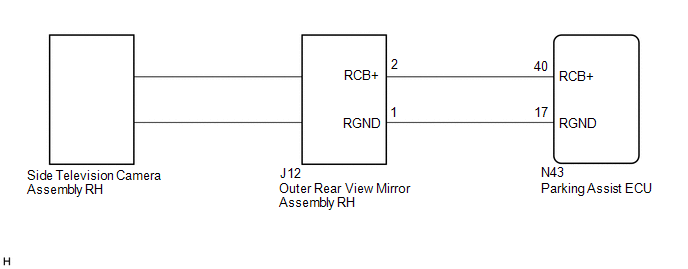
WIRING DIAGRAM
CAUTION / NOTICE / HINT
NOTICE:
-
When "!" is displayed on the multi-display assembly after the cable is disconnected from the negative (-) auxiliary battery terminal, correct the steering angle neutral point.
Click here
.gif)
-
Depending on the parts that are replaced or operations that are performed during vehicle inspection or maintenance, calibration of other systems as well as the panoramic view monitor system may be needed.
Click here
PROCEDURE
| 1. | CHECK FOR DTC |
(a) Clear the DTCs.
Chassis > Circumference Monitoring Camera Control Module > Clear DTCs(b) Check for DTCs.
Chassis > Circumference Monitoring Camera Control Module > Trouble CodesOK:
DTC C1684 is not output.
| OK | .gif) | USE SIMULATION METHOD TO CHECK |
|
.gif)
| 2. | CHECK HARNESS AND CONNECTOR (PARKING ASSIST ECU - OUTER REAR VIEW MIRROR ASSEMBLY RH) |
(a) Disconnect the N43 parking assist ECU connector.
(b) Disconnect the J12 outer rear view mirror assembly RH connector.
(c) Measure the resistance according to the value(s) in the table below.
Standard Resistance:
| Tester Connection | Condition | Specified Condition |
|---|---|---|
| N43-40 (RCB+) - J12-2 (RCB+) | Always | Below 1 Ω |
| N43-17 (RGND) - J12-1 (RGND) | Always | Below 1 Ω |
| N43-40 (RCB+) or J12-2 (RCB+) - Body ground | Always | 10 kΩ or higher |
| N43-17 (RGND) or J12-1 (RGND) - Body ground | Always | 10 kΩ or higher |
| NG | | REPAIR OR REPLACE HARNESS OR CONNECTOR |
|
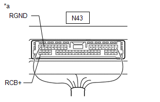
| 3. | CHECK PARKING ASSIST ECU (RCB+, RGND) |
| (a) Remove the parking assist ECU with the connector still connected. |
|
(b) Measure the resistance according to the value(s) in the table below.
Standard Resistance:
| Tester Connection | Condition | Specified Condition |
|---|---|---|
| N43-17 (RGND) - Body ground | Always | Below 1 Ω |
(c) Measure the voltage according to the value(s) in the table below.
Standard Voltage:
| Tester Connection | Condition | Specified Condition |
|---|---|---|
| N43-40 (RCB+) - N43-17 (RGND) | Power switch on (IG) | 5.5 to 7.05 V |
| NG | | REPLACE PARKING ASSIST ECU |
|
| 4. | REPLACE SIDE TELEVISION CAMERA ASSEMBLY RH |
(a) Replace the side television camera assembly RH with a new or normally functioning one.
Click here
|
| 5. | CHECK FOR DTC |
(a) Clear the DTCs.
Chassis > Circumference Monitoring Camera Control Module > Clear DTCs(b) Check for DTCs.
Chassis > Circumference Monitoring Camera Control Module > Trouble CodesOK:
DTCs C1684 is not output.
| OK | | END (SIDE TELEVISION CAMERA ASSEMBLY RH IS DEFECTIVE) |
| NG | | REPLACE OUTER REAR VIEW MIRROR ASSEMBLY LH |
READ NEXT:
 Driver Side Camera Video Sync Signal Malfunction (C1686)
DESCRIPTION This DTC is stored if the parking assist ECU judges as a result of its self check that a synchronization problem is occurring in the image signal sent from the driver side television camer
Over Current Detected in Driver Side Camera (C1687)
DESCRIPTION This DTC is stored if the parking assist ECU judges as a result of its self check that a synchronization problem is occurring in the image signal sent from the driver side television camer
Back Camera Initialization Incomplete (C1691)
DESCRIPTION This DTC is stored when the rear television camera assembly judges that the back camera initial setting has not been memorized (rear television camera assembly optical axis adjustment (bac
SEE MORE:
Installation
INSTALLATION PROCEDURE 1. INSTALL FUEL LID LOCK WITH MOTOR ASSEMBLY (a) Apply MP grease to the sliding parts of the fuel lid lock with motor assembly. (b) Connect the connector. (c) Engage the 2 claws. (d) Engage the clamp to install the fuel lid lock with motor assembly. 2. INSTALL FUEL FILLER OPEN
Disassembly
DISASSEMBLY PROCEDURE 1. REMOVE MOTOR COVER (a) Disconnect the connector. (b) Disengage the 2 clamps. (c) Disengage the 4 claws to remove the motor cover as shown in the illustration. Remove in this Direction 2. REMOVE SWING GRILLE ACTUATOR ASSEMBLY (a) Remove the swing gril
