Lexus ES: Short to +B in Outer Mirror Indicator(Slave) (C1AB1)
DESCRIPTION
This DTC is stored when the blind spot monitor sensor LH detects a short to +B in the outer rear view mirror indicator LH.
| DTC No. | Detection Item | DTC Detection Condition | Trouble Area |
|---|---|---|---|
| C1AB1 | Short to +B in Outer Mirror Indicator(Slave) | Both of the following conditions are met:
|
|
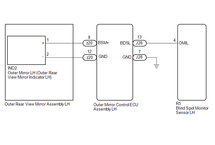
WIRING DIAGRAM
CAUTION / NOTICE / HINT
NOTICE:
When checking for DTCs, make sure that the blind spot monitor system is turned on.
PROCEDURE
| 1. | CHECK DTC |
(a) Turn the power switch off.
(b) Turn the power switch on (IG).
(c) Recheck for DTCs and check if the same DTC is output again.
Body Electrical > Blind Spot Monitor Slave > Trouble CodesOK:
No DTCs are output.
| OK |  | USE SIMULATION METHOD TO CHECK |
|

| 2. | CHECK HARNESS AND CONNECTOR (OUTER REAR VIEW MIRROR INDICATOR CIRCUIT) |
(a) Disconnect the R5 blind spot monitor sensor LH connector.
(b) Measure the voltage according to the value(s) in the table below.
Standard Voltage:
| Tester Connection | Condition | Specified Condition |
|---|---|---|
| R5-4 (OMIL) - Body ground | Power switch on (IG) | Below 1 V |
| OK | | REPLACE BLIND SPOT MONITOR SENSOR LH |
.gif)
|
| 3. | CHECK HARNESS AND CONNECTOR (OUTER REAR VIEW MIRROR INDICATOR CIRCUIT) |
(a) Disconnect the IND2 outer mirror LH connector.
(b) Measure the voltage according to the value(s) in the table below.
Standard Voltage:
| Tester Connection | Condition | Specified Condition |
|---|---|---|
| R5-4 (OMIL) - Body ground | Power switch on (IG) | Below 1 V |
| OK | | REPLACE OUTER MIRROR LH |
|
| 4. | CHECK HARNESS AND CONNECTOR (OUTER REAR VIEW MIRROR INDICATOR CIRCUIT) |
(a) Disconnect the z20 outer rear view mirror assembly LH connector.
(b) Measure the voltage according to the value(s) in the table below.
Standard Voltage:
| Tester Connection | Condition | Specified Condition |
|---|---|---|
| R5-4 (OMIL) - Body ground | Power switch on (IG) | Below 1 V |
| OK | | REPLACE OUTER REAR VIEW MIRROR ASSEMBLY LH |
|
| 5. | CHECK HARNESS AND CONNECTOR (OUTER REAR VIEW MIRROR INDICATOR CIRCUIT) |
(a) Disconnect the J28 outer mirror control ECU assembly LH connector.
(b) Measure the voltage according to the value(s) in the table below.
Standard Voltage:
| Tester Connection | Condition | Specified Condition |
|---|---|---|
| R5-4 (OMIL) - Body ground | Power switch on (IG) | Below 1 V |
| OK | | REPLACE OUTER MIRROR CONTROL ECU ASSEMBLY LH |
| NG | | REPAIR OR REPLACE HARNESS OR CONNECTOR |
READ NEXT:
 Short to GND in Outer Mirror Indicator(Master) (C1AB2)
DESCRIPTION This DTC is stored when the blind spot monitor sensor RH detects a short to ground in the outer rear view mirror indicator RH. DTC No. Detection Item DTC Detection Condition Troub
Short to GND in Outer Mirror Indicator(Slave) (C1AB3)
DESCRIPTION This DTC is stored when the blind spot monitor sensor LH detects a short to ground in the outer rear view mirror indicator LH. DTC No. Detection Item DTC Detection Condition Troub
Open in Outer Mirror Indicator(Master) (C1AB4)
DESCRIPTION This DTC is stored when the blind spot monitor sensor RH detects an open in the outer rear view mirror indicator RH. DTC No. Detection Item DTC Detection Condition Trouble Area
SEE MORE:
Parts Location
PARTS LOCATION ILLUSTRATION *1 ECM *2 FUEL TANK ASSEMBLY *3 FUEL PUMP CONTROL ECU *4 FUEL SUCTION TUBE WITH PUMP AND GAUGE ASSEMBLY - FUEL PUMP (for Low Pressure) - FUEL MAIN VALVE ASSEMBLY - FUEL SENDER GAUGE ASSEMBLY *5 FUEL TANK VENT TUBE ASSEMBLY - NO. 2 FUEL SENDER GAU
Washer Motor Circuit
DESCRIPTION When the windshield washer motor and pump assembly receives signals from the windshield wiper switch assembly it operates to spray washer fluid from the washer nozzle sub-assemblies. WIRING DIAGRAM CAUTION / NOTICE / HINT NOTICE:
Inspect the fuses for circuits related to this system
