Lexus ES: Short to GND in Outer Mirror Indicator(Master) (C1AB2)
DESCRIPTION
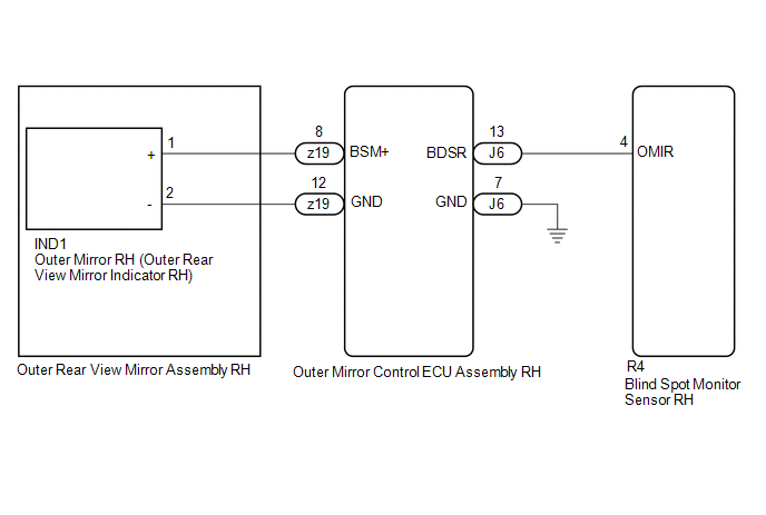
This DTC is stored when the blind spot monitor sensor RH detects a short to ground in the outer rear view mirror indicator RH.
| DTC No. | Detection Item | DTC Detection Condition | Trouble Area |
|---|---|---|---|
| C1AB2 | Short to GND in Outer Mirror Indicator(Master) | Both of the following conditions are met:
|
|
WIRING DIAGRAM
CAUTION / NOTICE / HINT
NOTICE:
When checking for DTCs, make sure that the blind spot monitor system is turned on.
PROCEDURE
| 1. | CHECK DTC |
(a) Turn the power switch off.
(b) Turn the power switch on (IG).
(c) Recheck for DTCs and check if the same DTC is output again.
Body Electrical > Blind Spot Monitor Master > Trouble CodesOK:
No DTCs are output.
| OK |  | USE SIMULATION METHOD TO CHECK |
|

| 2. | CHECK HARNESS AND CONNECTOR (BLIND SPOT MONITOR SENSOR RH - OUTER MIRROR CONTROL ECU ASSEMBLY RH) |
(a) Disconnect the R4 blind spot monitor sensor RH connector.
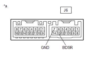
(b) Disconnect the J6 outer mirror control ECU assembly RH connector.
(c) Measure the resistance according to the value(s) in the table below.
Standard Resistance:
| Tester Connection | Condition | Always |
|---|---|---|
| R4-4 (OMIR) - Body ground | Always | 10 kΩ or higher |
| NG | | REPAIR OR REPLACE HARNESS OR CONNECTOR |
|
| 3. | INSPECT OUTER REAR VIEW MIRROR ASSEMBLY RH |
(a) Disconnect the z19 outer rear view mirror assembly RH connector.
(b) Disconnect the IND1 outer mirror RH connector.
(c) Measure the resistance according to the value(s) in the table below.
Standard Resistance:
| Tester Connection | Condition | Always |
|---|---|---|
| z19-8 (BSM+) - Body ground | Always | 10 kΩ or higher |
| NG | | REPLACE OUTER REAR VIEW MIRROR ASSEMBLY RH |
|
| 4. | INSPECT OUTER MIRROR CONTROL ECU ASSEMBLY RH |
| (a) Measure the resistance according to the value(s) in the table below. Standard Resistance:
|
|
| NG | | REPLACE OUTER MIRROR CONTROL ECU ASSEMBLY RH |
|
| 5. | INSPECT OUTER MIRROR RH |
(a) Remove the outer mirror RH.
Click here .gif)
(b) Inspect the outer rear view mirror indicator RH on the outer mirror RH.
Click here
| OK | | REPLACE BLIND SPOT MONITOR SENSOR RH |
| NG | | REPLACE OUTER MIRROR RH |
READ NEXT:
 Short to GND in Outer Mirror Indicator(Slave) (C1AB3)
DESCRIPTION This DTC is stored when the blind spot monitor sensor LH detects a short to ground in the outer rear view mirror indicator LH. DTC No. Detection Item DTC Detection Condition Troub
Open in Outer Mirror Indicator(Master) (C1AB4)
DESCRIPTION This DTC is stored when the blind spot monitor sensor RH detects an open in the outer rear view mirror indicator RH. DTC No. Detection Item DTC Detection Condition Trouble Area
Open in Outer Mirror Indicator(Slave) (C1AB5)
DESCRIPTION This DTC is stored when the blind spot monitor sensor LH detects an open in the outer rear view mirror indicator LH. DTC No. Detection Item DTC Detection Condition Trouble Area
SEE MORE:
Startability Malfunction (P160400)
DESCRIPTION This DTC is stored when the engine does not start even though the STA signal is input or when the engine takes a long time to start, and when the engine speed is low or the engine stalls just after the engine starts. Using the Techstream, the conditions present when the DTC was stored ca
Pressure Control Solenoid "C" Actuator Stuck Off (P07957F)
DESCRIPTION Based on signals from the transmission revolution sensors (NT and NC), the actual gear is detected. The ECM compares the actual gear with the shift schedule in the ECM memory to detect mechanical malfunctions of the solenoid valves, transmission valve body assembly and automatic transaxl
