Lexus ES: Short circuit in Power source circuit (C13A1)
DESCRIPTION
C13A1 is stored if the power supply relay in the parking brake ECU assembly has a short circuit.
C13A1 is stored if the power switch is off and a voltage of 2.5 V or higher is applied to the IG terminal and an electric parking brake switch assembly malfunction or wire harness malfunction between the switch and ECU occurs.
| DTC No. | Detection Item | DTC Detection Condition | Trouble Area | Memory | Note |
|---|---|---|---|---|---|
| C13A1 | Short circuit in Power source circuit | Both of following conditions are met:
|
| DTC stored | An electric parking brake system malfunction is displayed on the multi-information display. |
HINT:
DTC will be output when conditions for either of the patterns in the table above are met.
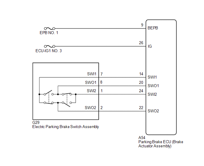
WIRING DIAGRAM
CAUTION / NOTICE / HINT
NOTICE:
- Inspect the fuses for circuits related to this system before performing the following procedure.
- The electric parking brake may still operate up to 20 seconds after the power switch is turned off. Before disconnecting connectors or fuses, turn the power switch off and wait 20 seconds or more.
- The parking brake indicator light blinks (red) when the power switch is turned on (IG) after replacing the parking brake ECU (brake actuator assembly). Operate the electric parking brake switch assembly to turn off the parking brake indicator light (red).
PROCEDURE
| 1. | CHECK HARNESS AND CONNECTOR (BEPB CIRCUIT) |
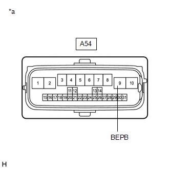
| *a | Front view of wire harness connector (to Parking Brake ECU (Brake Actuator Assembly)) |
(a) Turn the power switch off.
(b) Disconnect the A54 parking brake ECU (brake actuator assembly) connector.
(c) Measure the voltage according to the value(s) in the table below.
Standard Voltage:
| Tester Connection | Condition | Specified Condition |
|---|---|---|
| A54-9 (BEPB) - Body ground | Power switch off | 11 to 14 V |
| NG | .gif) | REPAIR OR REPLACE HARNESS OR CONNECTOR |
|
.gif)
| 2. | CHECK HARNESS AND CONNECTOR (PARKING BRAKE ECU (BRAKE ACTUATOR ASSEMBLY) - IG POWER SOURCE CIRCUIT) |
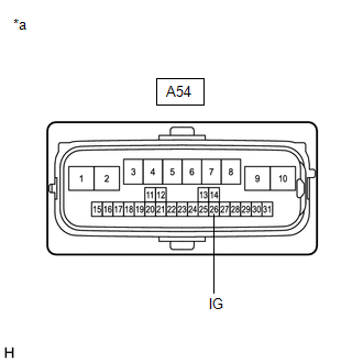
| *a | Front view of wire harness connector (to Parking Brake ECU (Brake Actuator Assembly)) |
(a) Turn the power switch off.
(b) Disconnect the A54 parking brake ECU (brake actuator assembly) connector.
(c) Measure the voltage according to the value(s) in the table below.
Standard Voltage:
| Tester Connection | Condition | Specified Condition |
|---|---|---|
| A54-26 (IG) - Body ground | Power switch off | Below 2.5 V |
| NG | | REPAIR OR REPLACE HARNESS OR CONNECTOR |
|
| 3. | INSPECT ELECTRIC PARKING BRAKE SWITCH ASSEMBLY |
(a) Remove the electric parking brake switch assembly.
Click here .gif)
(b) Inspect the electric parking brake switch assembly.
Click here
| NG | | REPLACE ELECTRIC PARKING BRAKE SWITCH ASSEMBLY |
|
| 4. | CHECK HARNESS AND CONNECTOR (PARKING BRAKE ECU (BRAKE ACTUATOR ASSEMBLY) - ELECTRIC PARKING BRAKE SWITCH ASSEMBLY) |
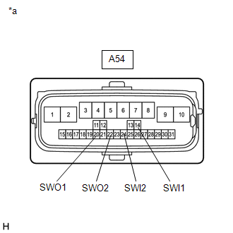
| *a | Front view of wire harness connector (to Parking Brake ECU (Brake Actuator Assembly)) |
(a) Disconnect the G29 electric parking brake switch assembly connector.
(b) Disconnect the A54 parking brake ECU (brake actuator assembly) connector.
(c) Measure the resistance according to the value(s) in the table below.
Standard Resistance:
| Tester Connection | Condition | Specified Condition |
|---|---|---|
| A54-14 (SWI1) - Body ground | Always | 10 kΩ or higher |
| A54-20 (SWO1) - Body ground | Always | 10 kΩ or higher |
| A54-24 (SWI2) - Body ground | Always | 10 kΩ or higher |
| A54-22 (SWO2) - Body ground | Always | 10 kΩ or higher |
| OK | | REPLACE PARKING BRAKE ECU (BRAKE ACTUATOR ASSEMBLY) |
| NG | | REPAIR OR REPLACE HARNESS OR CONNECTOR |
READ NEXT:
 Engine Switch/Power Switch Malfunction (C13A2)
DESCRIPTION When the power switch is turned on (IG), power is supplied to the parking brake ECU (brake actuator assembly). This DTC is stored if IG power source voltage is not supplied to the parking
Open or Short Circuit in Motor (C13A6)
DESCRIPTION DTC No. Detection Item DTC Detection Condition Trouble Area Memory Note C13A6 Open or Short Circuit in Motor Detection conditions (1)
Diagnosis Condition:
Power swi
Actuator Malfunction (C13A7)
DESCRIPTION DTC No. Detection Item DTC Detection Condition Trouble Area Memory Note C13A7 Actuator Malfunction Both of following conditions are met:
Electric parking brake is o
SEE MORE:
Removal
REMOVAL CAUTION / NOTICE / HINT The necessary procedures (adjustment, calibration, initialization, or registration) that must be performed after parts are removed and installed, or replaced during rear axle carrier sub-assembly removal/installation are shown below. Necessary Procedures After Parts R
Motor/Generator Shutdown Signal Stuck Off (P321E9F)
DTC SUMMARY MALFUNCTION DESCRIPTION The hybrid vehicle control ECU detects malfunctions which prevent the inverter with converter assembly emergency shutdown circuit (HSDN) from shutting down the hybrid control system. Detection is performed when the power switch is turned on (IG) and during the shu
