Lexus ES: Engine Switch/Power Switch Malfunction (C13A2)
DESCRIPTION
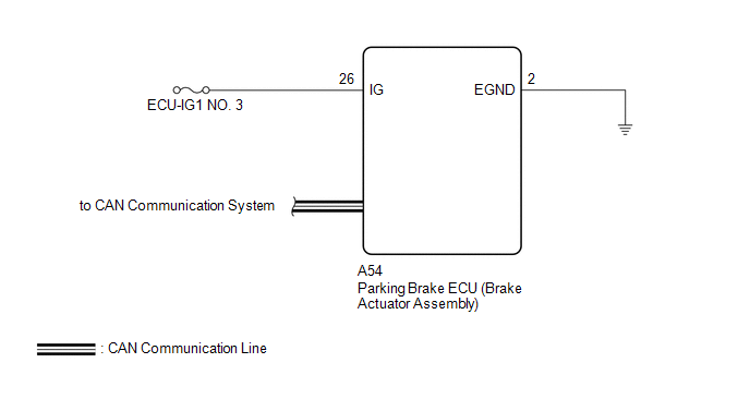
When the power switch is turned on (IG), power is supplied to the parking brake ECU (brake actuator assembly). This DTC is stored if IG power source voltage is not supplied to the parking brake ECU (brake actuator assembly) when communication with other ECUs is established.
| DTC No. | Detection Item | DTC Detection Condition | Trouble Area | Memory | Note |
|---|---|---|---|---|---|
| C13A2 | Engine Switch/Power Switch Malfunction | Both of following conditions are met:
|
| DTC stored | An electric parking brake system malfunction is displayed on the multi-information display. |
WIRING DIAGRAM
CAUTION / NOTICE / HINT
NOTICE:
- Inspect the fuses for circuits related to this system before performing the following procedure.
- The electric parking brake may still operate up to 20 seconds after the power switch is turned off. Before disconnecting connectors or fuses, turn the power switch off and wait 20 seconds or more.
- The parking brake indicator light blinks (red) when the power switch is turned on (IG) after replacing the parking brake ECU (brake actuator assembly). Operate the electric parking brake switch assembly to turn off the parking brake indicator light (red).
PROCEDURE
| 1. | READ VALUE USING TECHSTREAM (IG SWITCH) |
(a) Turn the power switch off.
(b) Connect the Techstream to the DLC3.
(c) Turn the power switch on (IG).
(d) Turn the Techstream on.
(e) Enter the following menus: Chassis / Electric Parking Brake / Data List.
(f) Read the Data List according to the display on the Techstream.
Chassis > Electric Parking Brake > Data List| Tester Display | Measurement Item | Range | Normal Condition | Diagnostic Note |
|---|---|---|---|---|
| IG Switch | IG power source status | OFF or ON | OFF: IG power source voltage is not input to skid control ECU (brake booster with master cylinder assembly) ON: IG power source voltage is input to skid control ECU (brake booster with master cylinder assembly) | - |
| Tester Display |
|---|
| IG Switch |
| NG | .gif) | GO TO STEP 3 |
|
.gif)
| 2. | CHECK DTC |
(a) Clear the DTCs.
Chassis > Electric Parking Brake > Clear DTCs(b) Turn the power switch off.
(c) Check for DTCs.
Chassis > Electric Parking Brake > Trouble Codes| Result | Proceed to |
|---|---|
| DTCs are output | A |
| DTCs are not output | B |
| A | | REPLACE PARKING BRAKE ECU (BRAKE ACTUATOR ASSEMBLY) |
| B | | USE SIMULATION METHOD TO CHECK |
| 3. | CHECK HARNESS AND CONNECTOR (PARKING BRAKE ECU (BRAKE ACTUATOR ASSEMBLY) - POWER SOURCE AND BODY GROUND) |
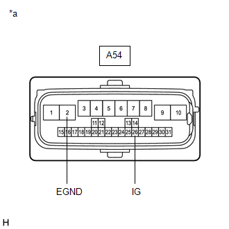
| *a | Front view of wire harness connector (to Parking Brake ECU (Brake Actuator Assembly)) |
(a) Disconnect the A54 parking brake ECU (brake actuator assembly) connectors.
(b) Turn the power switch on (IG).
(c) Measure the voltage according to the value(s) in the table below.
Standard Voltage:
| Tester Connection | Condition | Specified Condition |
|---|---|---|
| A54-26 (IG) - Body ground | Power switch on (IG) | 8 to 16 V |
(d) Turn the power switch off.
(e) Measure the resistance according to the value(s) in the table below.
Standard Resistance:
| Tester Connection | Condition | Specified Condition |
|---|---|---|
| A54-2 (EGND) - Body ground | Always | Below 1 Ω |
| OK | | REPAIR IG POWER SOURCE CIRCUIT |
| NG | | REPAIR OR REPLACE HARNESS OR CONNECTOR |
READ NEXT:
 Open or Short Circuit in Motor (C13A6)
DESCRIPTION DTC No. Detection Item DTC Detection Condition Trouble Area Memory Note C13A6 Open or Short Circuit in Motor Detection conditions (1)
Diagnosis Condition:
Power swi
Actuator Malfunction (C13A7)
DESCRIPTION DTC No. Detection Item DTC Detection Condition Trouble Area Memory Note C13A7 Actuator Malfunction Both of following conditions are met:
Electric parking brake is o
Brake System Malfunction (C13A9)
DESCRIPTION The parking brake ECU (brake actuator assembly) receives the wheel speed signal of each wheel from the skid control ECU (brake booster with master cylinder assembly) via CAN communication.
SEE MORE:
Generator Phase U Current Sensor Signal Bias Level Out of Range / Zero Adjustment Failure (P0E0028,...,P0E0828)
DTC SUMMARY MALFUNCTION DESCRIPTION These DTCs indicate that the current sensor value is abnormal. The cause of this malfunction may be one of the following: Internal inverter malfunction
Current sensor malfunction
Inverter with converter assembly internal circuit malfunction
DESCRIPTION The
Back Camera Disconnected (C1622)
DESCRIPTION This DTC is stored if the radio receiver assembly judges that the signals or signal lines between the rear television camera assembly and the multi-display assembly are not normal as a result of its self check. DTC No. Detection Item DTC Detection Condition Trouble Area C162
