Lexus ES: Open or Short Circuit in Motor (C13A6)
DESCRIPTION
| DTC No. | Detection Item | DTC Detection Condition | Trouble Area | Memory | Note |
|---|---|---|---|---|---|
| C13A6 | Open or Short Circuit in Motor | Detection conditions (1)
Detection conditions (2)
Detection conditions (3)
|
| DTC stored | An electric parking brake system malfunction is displayed on the multi-information display. |
| Vehicle Condition | ||||||
|---|---|---|---|---|---|---|
| Pattern 1 | Pattern 2 | Pattern 3 | Pattern 4 | Pattern 5 | ||
| Diagnosis Condition | Power switch on (IG) | ○ | - | - | - | - |
| Electric parking brake switch assembly pushed to lock side with power switch off | - | ○ | - | - | - | |
| Power switch turned from off to on (IG) | - | - | ○ | - | - | |
| With power switch on (IG), electric parking brake switch assembly is changed from lock to release 3 times repeatedly | - | - | - | ○ | - | |
| With power switch on (IG), electric parking brake switch assembly is changed from release to lock 3 times repeatedly | - | - | - | - | - | |
| Malfunction Status | Voltage of power supplied to ECU is normal but malfunction exists in parking brake motor circuit | ○ | ○ | - | - | ○ |
| Overcurrent is detected in the parking brake motor circuit continuously. | - | - | ○ | ○ | ○ | |
| Detection Time | Approximately 1 to 2 seconds | Approximately 1 to 2 seconds | Approximately 1 second | - | - | |
| Number of Trips | 1 trip | 1 trip | 1 trip | 1 trip | 1 trip | |
HINT:
DTC will be output when conditions for either of the patterns in the table above are met.
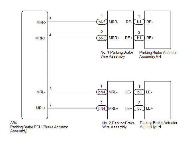
WIRING DIAGRAM
CAUTION / NOTICE / HINT
NOTICE:
- The electric parking brake may still operate up to 20 seconds after the power switch is turned off. Before disconnecting connectors or fuses, turn the power switch off and wait 20 seconds or more.
- The parking brake indicator light blinks (red) when the power switch is turned on (IG) after replacing the parking brake ECU (brake actuator assembly). Operate the electric parking brake switch assembly to turn off the parking brake indicator light (red).
PROCEDURE
| 1. | READ VALUE USING TECHSTREAM (PERMISSION OF RH INTERLOCKING PKB LOCK / PERMISSION OF LH INTERLOCKING PKB LOCK) |
(a) Turn the power switch off.
(b) Connect the Techstream to the DLC3.
(c) Turn the power switch on (IG).
(d) Turn the Techstream on.
(e) Enter the following menus: Chassis / Electric Parking Brake / Data List.
(f) Read the Data List according to the display on the Techstream.
Chassis > Electric Parking Brake > Data List| Tester Display | Measurement Item | Range | Normal Condition | Diagnostic Note |
|---|---|---|---|---|
| Permission of RH Interlocking PKB Lock | Parking brake actuator assembly RH parking brake lock control permission status | OK or NG | OK | - |
| Permission of LH Interlocking PKB Lock | Parking brake actuator assembly RH parking brake lock control permission status | OK or NG | OK | - |
| Tester Display |
|---|
| Permission of RH Interlocking PKB Lock |
| Permission of LH Interlocking PKB Lock |
|
.gif)
| 2. | INSPECT PARKING BRAKE WIRE ASSEMBLY |
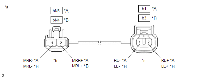
| *A | RH | *B | LH |
| *a | Front view of Parking Brake Wire Assembly | *b | (to wire harness connector) |
| *c | (to Parking Brake Actuator Assembly) | - | - |
(a) Remove the parking brake wire assembly.
(b) Check the parking brake wire assembly for damage.
OK:
No damage.
HINT:
If damaged, there may be a short in the wire harness or a short to ground.
(c) Inspect the parking brake wire assembly.
Standard Resistance:
RH| Tester Connection | Condition | Specified Condition |
|---|---|---|
| bN3-1 (MRR-) - b1-1 (RE-) | Always | Below 1 Ω |
| bN3-1 (MRR-) - b1-2 (RE+) | Always | 10 kΩ or higher |
| bN3-1 (MRR-) or b1-1 (RE-) - Body ground | Always | 10 kΩ or higher |
| bN3-2 (MRR+) - b1-2 (RE+) | Always | Below 1 Ω |
| bN3-2 (MRR+) - b1-1 (RE-) | Always | 10 kΩ or higher |
| bN3-2 (MRR+) or b1-2 (RE+) - Body ground | Always | 10 kΩ or higher |
| Tester Connection | Condition | Specified Condition |
|---|---|---|
| bN4-1 (MRL-) - b3-1 (LE-) | Always | Below 1 Ω |
| bN4-1 (MRL-) - b3-2 (LE+) | Always | 10 kΩ or higher |
| bN4-1 (MRL-) or b3-1 (LE-) - Body ground | Always | 10 kΩ or higher |
| bN4-2 (MRL+) - b3-2 (LE+) | Always | Below 1 Ω |
| bN4-2 (MRL+) - b3-1 (LE-) | Always | 10 kΩ or higher |
| bN4-2 (MRL+) or b3-2 (LE+) - Body ground | Always | 10 kΩ or higher |
| NG | .gif) | REPLACE PARKING BRAKE WIRE ASSEMBLY |
|
| 3. | CHECK HARNESS AND CONNECTOR (PARKING BRAKE ECU (BRAKE ACTUATOR ASSEMBLY) - PARKING BRAKE ACTUATOR ASSEMBLY) |
(a) Turn the power switch off.
(b) Make sure the parking brake wire assembly is securely installed.
(c) Disconnect the A54 parking brake ECU (brake actuator assembly) connector.
(d) Disconnect the b1 or b3 parking brake actuator assembly connector.
(e) Measure the resistance according to the value(s) in the table below.
Standard Resistance:
RH| Tester Connection | Condition | Specified Condition |
|---|---|---|
| A54-4 (MRR+) - b1-2 (RE+) | Always | Below 1 Ω |
| A54-3 (MRR-) - b1-1 (RE-) | Always | Below 1 Ω |
| A54-4 (MRR+) or b1-2 (RE+) - Body ground | Always | 10 kΩ or higher |
| A54-3 (MRR-) or b1-1 (RE-) - Body ground | Always | 10 kΩ or higher |
| Tester Connection | Condition | Specified Condition |
|---|---|---|
| A54-7 (MRL+) - b3-2 (LE+) | Always | Below 1 Ω |
| A54-8 (MRL-) - b3-1 (LE-) | Always | Below 1 Ω |
| A54-7 (MRL+) or b3-2 (LE+) - Body ground | Always | 10 kΩ or higher |
| A54-8 (MRL-) or b3-1 (LE-) - Body ground | Always | 10 kΩ or higher |
| NG | | REPAIR OR REPLACE HARNESS OR CONNECTOR |
|
| 4. | INSPECT PARKING BRAKE ACTUATOR ASSEMBLY |
(a) Remove the parking brake actuator assembly.
Click here .gif)
(b) Inspect the parking brake actuator assembly.
Click here
| OK | | REPLACE PARKING BRAKE ECU (BRAKE ACTUATOR ASSEMBLY) |
| NG | | REPLACE PARKING BRAKE ACTUATOR ASSEMBLY |
READ NEXT:
 Actuator Malfunction (C13A7)
DESCRIPTION DTC No. Detection Item DTC Detection Condition Trouble Area Memory Note C13A7 Actuator Malfunction Both of following conditions are met:
Electric parking brake is o
Brake System Malfunction (C13A9)
DESCRIPTION The parking brake ECU (brake actuator assembly) receives the wheel speed signal of each wheel from the skid control ECU (brake booster with master cylinder assembly) via CAN communication.
EPB High Temperature (C13AA)
DESCRIPTION If the electric parking brake is used continuously, system operation is stopped to prevent the parking brake actuator assembly from overheating. This DTC is stored when system operation is
SEE MORE:
Installation
INSTALLATION PROCEDURE 1. INSTALL FUEL LID LOCK WITH MOTOR ASSEMBLY (a) Apply MP grease to the sliding parts of the fuel lid lock with motor assembly. (b) Connect the connector. (c) Engage the 2 claws. (d) Engage the clamp to install the fuel lid lock with motor assembly. 2. INSTALL FUEL FILLER OPEN
Installation
INSTALLATION PROCEDURE 1. INSTALL HAZARD WARNING SIGNAL SWITCH ASSEMBLY (a) Engage the 2 claws to install the hazard warning signal switch assembly. Install in this Direction 2. INSTALL NO. 2 INSTRUMENT PANEL REGISTER ASSEMBLY Click here 3. INSTALL UPPER INSTRUMENT PANEL FINISH PANEL SUB
