Lexus ES: Shift Paddle Switch Circuit
DESCRIPTION
Moving the shift lever to S enables the shift range to be selected. The shift range can be selected by operating the "+" or "-" shift paddle switch.
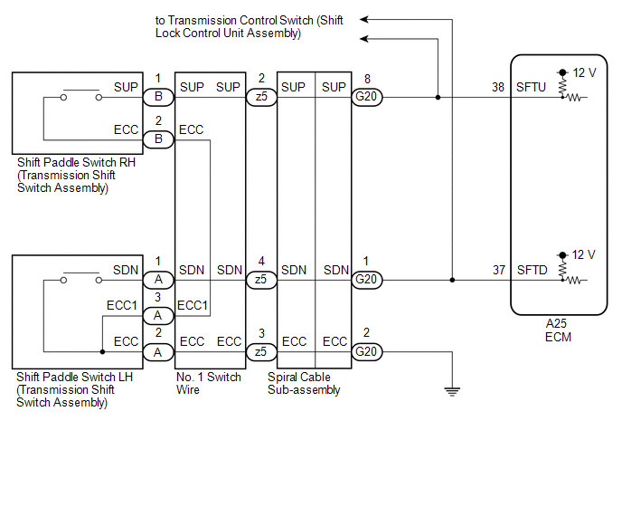
WIRING DIAGRAM
CAUTION / NOTICE / HINT
NOTICE:
After turning the engine switch off, waiting time may be required before disconnecting the cable from the negative (-) battery terminal. Therefore, make sure to read the disconnecting the cable from the negative (-) battery terminal notices before proceeding with work.
Click here .gif)
PROCEDURE
| 1. | READ VALUE USING TECHSTREAM (SPORT SHIFT SWITCH STATUS) |
(a) Connect the Techstream to the DLC3.
(b) Turn the engine switch on (IG).
(c) Turn the Techstream on.
(d) Enter the following menus: Powertrain / Engine / Data List.
(e) According to the display on the Techstream, read the Data List.
Powertrain > Engine > Data List| Tester Display | Measurement Item | Range | Normal Condition | Diagnostic Note |
|---|---|---|---|---|
| Sport Shift Up SW | Sport shift up switch status | ON or OFF |
| - |
| Sport Shift Down SW | Sport shift down switch status | ON or OFF |
| - |
| Tester Display |
|---|
| Sport Shift Up SW |
| Sport Shift Down SW |
| Result | Proceed to |
|---|---|
| Data List values are normal | A |
| Data List values are not normal | B |
| A | .gif) | CHECK FOR INTERMITTENT PROBLEMS |
|
.gif)
| 2. | CHECK HARNESS AND CONNECTOR (SHIFT PADDLE SWITCH CIRCUIT) |
(a) Disconnect the A25 ECM connector.
(b) Measure the resistance according to the value(s) in the table below.
Standard Resistance:
| Tester Connection | Condition | Specified Condition |
|---|---|---|
| A25-38 (SFTU) - Body ground | "+" (Up shift) shift paddle switch operated and held | Below 2.5 Ω |
| "+" (Up shift) shift paddle switch not operated | 1 MΩ or higher | |
| A25-37 (SFTD) - Body ground | "-" (Down shift) shift paddle switch operated and held | Below 2.5 Ω |
| "-" (Down shift) shift paddle switch not operated | 1 MΩ or higher |
| OK | | PROCEED TO NEXT SUSPECTED AREA SHOWN IN PROBLEM SYMPTOMS TABLE |
|
| 3. | CHECK HARNESS AND CONNECTOR (SPIRAL CABLE SUB-ASSEMBLY - ECM) |
(a) Disconnect the G20 spiral cable sub-assembly connector.
(b) Disconnect the A25 ECM connector.
(c) Measure the resistance according to the value(s) in the table below.
Standard Resistance:
| Tester Connection | Condition | Specified Condition |
|---|---|---|
| A25-38 (SFTU) - G20-8 (SUP) | Always | Below 1 Ω |
| A25-37 (SFTD) - G20-1 (SDN) | Always | Below 1 Ω |
| A25-38 (SFTU) or G20-8 (SUP) - Body ground | Always | 10 kΩ or higher |
| A25-37 (SFTD) or G20-1 (SDN) - Body ground | Always | 10 kΩ or higher |
| NG | | REPAIR OR REPLACE HARNESS OR CONNECTOR (SPIRAL CABLE SUB-ASSEMBLY - ECM) |
|
| 4. | CHECK HARNESS AND CONNECTOR (SPIRAL CABLE SUB-ASSEMBLY - BODY GROUND) |
(a) Disconnect the G20 spiral cable sub-assembly connector.
(b) Measure the resistance according to the value(s) in the table below.
Standard Resistance:
| Tester Connection | Condition | Specified Condition |
|---|---|---|
| G20-2 (ECC) - Body ground | Always | Below 1 Ω |
| NG | | REPAIR OR REPLACE HARNESS OR CONNECTOR (SPIRAL CABLE SUB-ASSEMBLY - BODY GROUND) |
|
| 5. | INSPECT SPIRAL CABLE SUB-ASSEMBLY |
(a) Inspect the spiral cable sub-assembly.
Click here
| NG | | REPLACE SPIRAL CABLE SUB-ASSEMBLY |
|
| 6. | INSPECT SHIFT PADDLE SWITCH LH (TRANSMISSION SHIFT SWITCH ASSEMBLY) |
| (a) Remove the shift paddle switch LH (transmission shift switch assembly). Click here |
|
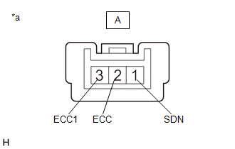
(b) Measure the resistance according to the value(s) in the table below.
Standard Resistance:
| Tester Connection | Condition | Specified Condition |
|---|---|---|
| A-1 (SDN) - A-2 (ECC) | "-" (Down shift) shift paddle switch operated and held | Below 2.5 Ω |
| "-" (Down shift) shift paddle switch not operated | 1 MΩ or higher | |
| A-1 (SDN) - A-3 (ECC1) | "-" (Down shift) shift paddle switch operated and held | Below 2.5 Ω |
| "-" (Down shift) shift paddle switch not operated | 1 MΩ or higher |
| NG | | REPLACE SHIFT PADDLE SWITCH LH (TRANSMISSION SHIFT SWITCH ASSEMBLY) |
|
| 7. | INSPECT SHIFT PADDLE SWITCH RH (TRANSMISSION SHIFT SWITCH ASSEMBLY) |
| (a) Remove the shift paddle switch RH (transmission shift switch assembly). Click here |
|
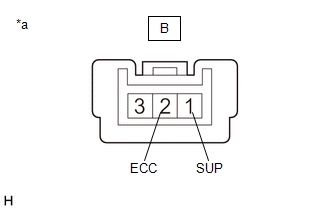
(b) Measure the resistance according to the value(s) in the table below.
Standard Resistance:
| Tester Connection | Condition | Specified Condition |
|---|---|---|
| B-1 (SUP) - B-2 (ECC) | "+" (Up shift) shift paddle switch operated and held | Below 2.5 Ω |
| "+" (Up shift) shift paddle switch not operated | 1 MΩ or higher |
| NG | | REPLACE SHIFT PADDLE SWITCH RH (TRANSMISSION SHIFT SWITCH ASSEMBLY) |
|
| 8. | INSPECT NO. 1 SWITCH WIRE |
| (a) Install the shift paddle switch LH and RH (transmission shift switch assembly). Click here |
|
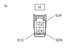
(b) Disconnect the z5 No. 1 switch wire connector.
(c) Measure the resistance according to the value(s) in the table below.
Standard Resistance:
| Tester Connection | Condition | Specified Condition |
|---|---|---|
| z5-2 (SUP) - z5-3 (ECC) | "+" (Up shift) shift paddle switch operated and held | Below 2.5 Ω |
| "+" (Up shift) shift paddle switch not operated | 1 MΩ or higher | |
| z5-4 (SDN) - z5-3 (ECC) | "-" (Down shift) shift paddle switch operated and held | Below 2.5 Ω |
| "-" (Down shift) shift paddle switch not operated | 1 MΩ or higher |
| OK | | PROCEED TO NEXT SUSPECTED AREA SHOWN IN PROBLEM SYMPTOMS TABLE |
| NG | | REPLACE NO. 1 SWITCH WIRE |
READ NEXT:
 System Diagram
SYSTEM DIAGRAM
System Diagram
SYSTEM DIAGRAM
Terminals Of Ecm
TERMINALS OF ECM ECM HINT: The standard voltage and resistance of each ECM terminal is shown in the table below. In the table, first follow the information under "Condition". Look under "Terminal No.
SEE MORE:
Terminals Of Ecu
TERMINALS OF ECU DCM (TELEMATICS TRANSCEIVER) *a to Telephone Antenna (Sub) *b to GPS Antenna *c to Telephone Antenna (Main) - - Terminal No. (Symbol) Wiring Color Terminal Description Condition Specified Condition G130-1 (USB-) - USB communication line -
Inspection
INSPECTION PROCEDURE 1. INSPECT KNOCK CONTROL SENSOR (a) Measure the resistance according to the value(s) in the table below. Standard Resistance: Tester Connection Condition Specified Condition 1 - 2 25°C (77°F) 120 to 280 kΩ If the result is not as specified, replace the k
