Lexus ES: Shift Lever Knob
Components
COMPONENTS
ILLUSTRATION
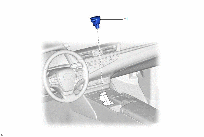
| *1 | SHIFT LEVER KNOB SUB-ASSEMBLY | - | - |
Installation
INSTALLATION
PROCEDURE
1. INSTALL SHIFT LEVER KNOB SUB-ASSEMBLY
| (a) Install the shift lever knob sub-assembly to the transmission floor shift assembly. |
|
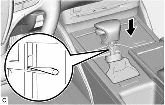
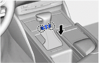
| (b) Engage the 2 claws to connect the shifting hole cover sub-assembly as shown in the illustration. NOTICE: Make sure that the shifting hole cover sub-assembly does not twist after installing the shift lever knob sub-assembly. |
|
Removal
REMOVAL
PROCEDURE
1. REMOVE SHIFT LEVER KNOB SUB-ASSEMBLY
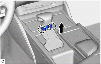
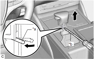
| (a) Disengage the 2 claws to disconnect the shifting hole cover sub-assembly as shown in the illustration. |
|
| (b) Using a screwdriver with its tip wrapped with protective tape, expand the left side of the clip and remove the shift lever knob sub-assembly from the transmission floor shift assembly as shown in the illustration. NOTICE: Be careful not to damage the shift lever knob sub-assembly. |
|
READ NEXT:
 Adjustment
ADJUSTMENT PROCEDURE 1. SECURE VEHICLE (a) Fully apply the parking brake and chock a wheel. CAUTION:
Make sure to apply the parking brake and chock a wheel before performing this procedure.
If th
Components
COMPONENTS ILLUSTRATION *1 FRONT WHEEL OPENING EXTENSION PAD RH *2 FRONT WHEEL OPENING EXTENSION PAD LH *3 NO. 1 ENGINE UNDER COVER *4 NO. 2 ENGINE UNDER COVER ASSEMBLY N*m
SEE MORE:
Removal
REMOVAL CAUTION / NOTICE / HINT The necessary procedures (adjustment, calibration, initialization, or registration) that must be performed after parts are removed and installed, or replaced during No. 2 clearance warning buzzer removal/installation are shown below. Necessary Procedure After Parts Re
Brake Hydraulic Pressure Malfunction (C164F)
DESCRIPTION When a malfunction signal sent from the skid control ECU via CAN communication is detected by the clearance warning ECU assembly, DTC C164F is stored. DTC No. Detection Item DTC Detection Condition Trouble Area C164F Brake Hydraulic Pressure Malfunction Brake master cyli
