Lexus ES: Right Electric Parking Brake Actuator Control Circuit Open (C061013)
DESCRIPTION
| DTC No. | Detection Item | DTC Detection Condition | Trouble Area | Memory | Note |
|---|---|---|---|---|---|
| C061013 | Right Electric Parking Brake Actuator Control Circuit Open |
|
| DTC stored | An electric parking brake system malfunction is displayed on the multi-information display. |
WIRING DIAGRAM
Click here .gif)
CAUTION / NOTICE / HINT
NOTICE:
- The electric parking brake may still operate up to 20 seconds after the engine switch is turned off. Before disconnecting connectors or fuses, turn the engine switch off and wait 20 seconds or more.
-
After replacing the skid control ECU (brake actuator assembly), perform acceleration sensor zero point calibration and store system information memorization.
Click here
- When replacing the skid control ECU (brake actuator assembly), operate the electric parking brake switch assembly as the parking brake indicator light blinks (red) when the engine switch is first turned on (IG).
PROCEDURE
| 1. | INSPECT NO. 1 PARKING BRAKE WIRE ASSEMBLY |
(a) Turn the engine switch off.
(b) Make sure that there is no looseness at the locking part and the connecting part of the connectors.
OK:
The connector is securely connected.
(c) Disconnect the bN3 and b1 No. 1 parking brake wire assembly connectors.
(d) Check both the connector case and the terminals for deformation and corrosion.
OK:
No deformation or corrosion.
(e) Measure the resistance according to the value(s) in the table below.
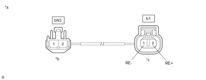
| *a | Front view of No. 1 Parking Brake Wire Assembly | *b | (to wire harness connector) |
| *c | (to Parking Brake Actuator Assembly RH) | - | - |
Standard Resistance:
| Tester Connection | Condition | Specified Condition |
|---|---|---|
| bN3-2 - b1-2 (RE+) | Always | Below 1 Ω |
| bN3-2 - Other terminals | Always | 10 kΩ or higher |
| bN3-1 - b1-1 (RE-) | Always | Below 1 Ω |
| bN3-1 - Other terminals | Always | 10 kΩ or higher |
| NG |  | REPLACE NO. 1 PARKING BRAKE WIRE ASSEMBLY |
|

| 2. | CHECK HARNESS AND CONNECTOR (SKID CONTROL ECU (BRAKE ACTUATOR ASSEMBLY) - PARKING BRAKE ACTUATOR ASSEMBLY RH) |
(a) Turn the engine switch off.
(b) Make sure the No. 1 parking brake wire assembly is securely installed.
(c) Disconnect the A40 skid control ECU (brake actuator assembly) connector.
(d) Disconnect the b1 parking brake actuator assembly RH connector.
(e) Measure the resistance according to the value(s) in the table below.
Standard Resistance:
| Tester Connection | Condition | Specified Condition |
|---|---|---|
| A40-2 (MRR+) - b1-2 (RE+) | Always | Below 1 Ω |
| A40-3 (MRR-) - b1-1 (RE-) | Always | Below 1 Ω |
| NG | | REPAIR OR REPLACE HARNESS OR CONNECTOR |
|
| 3. | INSPECT PARKING BRAKE ACTUATOR ASSEMBLY RH |
(a) Remove the parking brake actuator assembly RH.
Click here
(b) Inspect the parking brake actuator assembly RH.
Click here
| OK | | REPLACE SKID CONTROL ECU (BRAKE ACTUATOR ASSEMBLY) |
| NG | | REPLACE PARKING BRAKE ACTUATOR ASSEMBLY RH |
READ NEXT:
 Data List / Active Test
DATA LIST / ACTIVE TEST READ DATA LIST HINT: Using the Techstream to read the Data List allows the values or states of switches, sensors, actuators and other items to be read without removing any part
Diagnostic Trouble Code Chart
DIAGNOSTIC TROUBLE CODE CHART Electric Parking Brake System DTC No. Detection Item Memory Note Link C059704 Brake System Control Module "A" System Internal Failure DTC stored An e
Dtc Check / Clear
DTC CHECK / CLEAR CHECK DTC AND FREEZE FRAME DATA (USING TECHSTREAM) (a) Turn the engine switch off. (b) Connect the Techstream to the DLC3. (c) Turn the engine switch on (IG). (d) Turn the Techstream
SEE MORE:
Drive Mode Select Switch Circuit
DESCRIPTION The characteristics of the electronic throttle and EPS operation change according to operation of the drive mode select switch (combination switch assembly). WIRING DIAGRAM PROCEDURE 1. CHECK THE PROBLEM SYMPTOMS (a) Check each symptom by checking the suspected areas in the tab
Installation
INSTALLATION PROCEDURE 1. INSTALL REAR ENGINE OIL SEAL (a) Using height adjustment attachments and plate lift attachments, place the engine assembly on a flat level surface. NOTICE:
Using height adjustment attachments and plate lift attachments, keep the engine assembly level.
To prevent the No
