Lexus ES: Drive Belt
Components
COMPONENTS
ILLUSTRATION
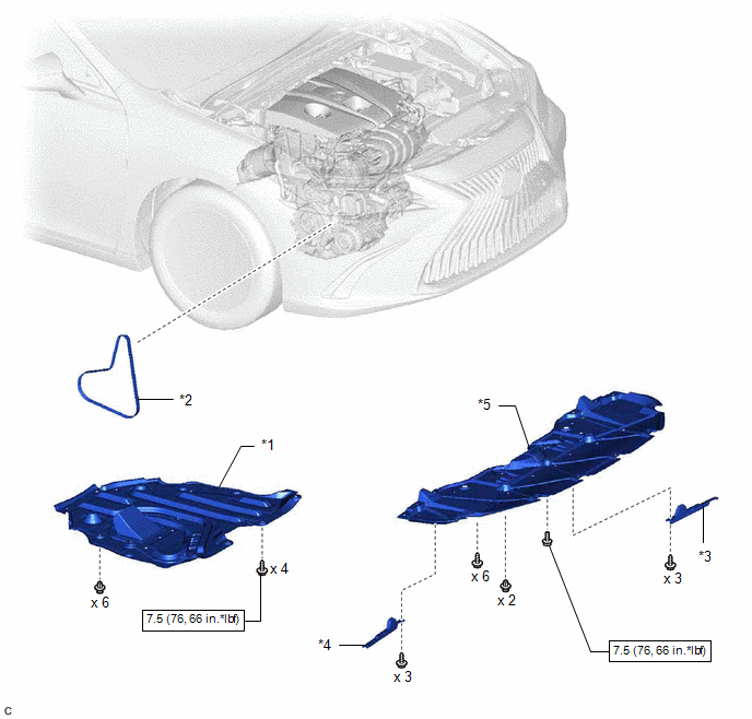
| *1 | NO. 2 ENGINE UNDER COVER ASSEMBLY | *2 | V-RIBBED BELT |
| *3 | FRONT WHEEL OPENING EXTENSION PAD LH | *4 | FRONT WHEEL OPENING EXTENSION PAD RH |
| *5 | NO. 1 ENGINE UNDER COVER | - | - |
.png) | N*m (kgf*cm, ft.*lbf): Specified torque | - | - |
On-vehicle Inspection
ON-VEHICLE INSPECTION
CAUTION / NOTICE / HINT
CAUTION:
To prevent injury due to contact with an operating V-ribbed belt or cooling fan, keep your hands and clothing away from the V-ribbed belt and cooling fans when working in the engine compartment with the engine running or the engine switch on (IG).
.png)
PROCEDURE
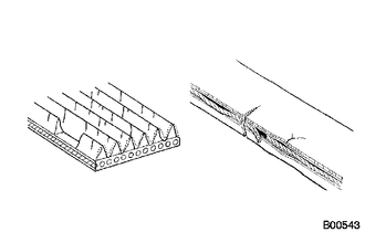
1. INSPECT V-RIBBED BELT
| (a) Check the V-ribbed belt for wear, cracks or other signs of damage. If any of the following defects is found, replace the V-ribbed belt.
|
|
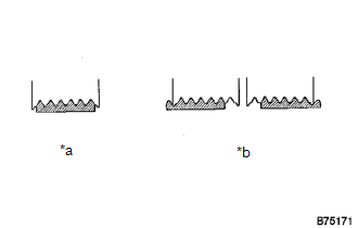
| (b) Check that the V-ribbed belt fits properly in the ribbed grooves. HINT: Check with your hand to confirm that the V-ribbed belt has not slipped out of the grooves on the bottom of the pulley. If it has slipped out, replace the V-ribbed belt. Install a new V-ribbed belt correctly. |
|
Removal
REMOVAL
PROCEDURE
1. REMOVE FRONT WHEEL OPENING EXTENSION PAD LH
Click here .gif)
2. REMOVE FRONT WHEEL OPENING EXTENSION PAD RH
Click here
3. REMOVE NO. 1 ENGINE UNDER COVER
Click here
4. REMOVE NO. 2 ENGINE UNDER COVER ASSEMBLY
Click here
5. REMOVE V-RIBBED BELT
Click here
READ NEXT:
 On-vehicle Inspection
ON-VEHICLE INSPECTION CAUTION / NOTICE / HINT CAUTION: To prevent injury due to contact with an operating V-ribbed belt or cooling fan, keep your hands and clothing away from the V-ribbed belt and coo
SEE MORE:
Components
COMPONENTS ILLUSTRATION *1 GLOVE COMPARTMENT DOOR ASSEMBLY *2 LUGGAGE DOOR OPENING CANCEL SWITCH ASSEMBLY
Components
COMPONENTS ILLUSTRATION *1 REAR DRIVE SHAFT OIL SEAL LH - - ● Non-reusable part MP grease
