Lexus ES: Reassembly
REASSEMBLY
PROCEDURE
1. INSTALL SPARK PLUG TUBE
HINT:
When using a new cylinder head sub-assembly, the spark plug tubes must be replaced.
| (a) Apply adhesive to a new spark plug tube as shown in the illustration. Adhesive: Toyota Genuine Adhesive 1324, Three Bond 1324 or equivalent Standard Application Width: 1.0 to 7.0 mm (0.0394 to 0.276 in.) Distance: 1.0 mm (0.0394 in.) NOTICE:
|
|
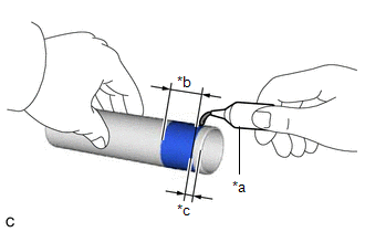
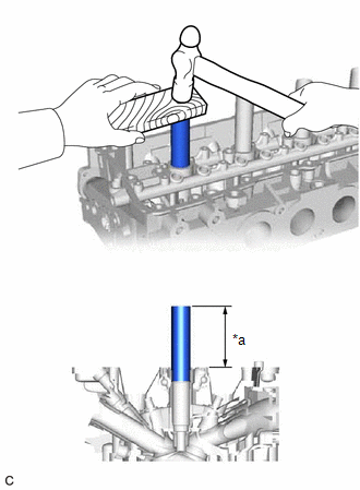
| (b) Using a wooden block and hammer, tap in the 4 spark plug tubes to the specified protrusion height. Standard Protrusion Height: 75.7 to 76.7 mm (2.98 to 3.02 in.) NOTICE: To avoid tapping in the spark plug tube too far, measure the protrusion height while tapping it. |
|
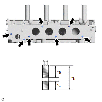
2. INSTALL STUD BOLT
NOTICE:
If a stud bolt is deformed or its threads are damaged, replace it.
| (a) Using an E8 "TORX" socket wrench, install the 7 stud bolts. Torque: 6.5 N·m {66 kgf·cm, 58 in·lbf} |
|
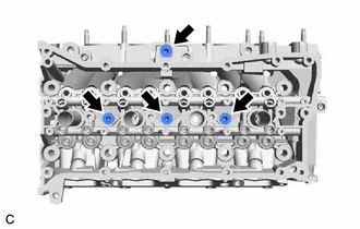
3. INSTALL NO. 1 STRAIGHT SCREW PLUG
HINT:
If coolant leaks from a No. 1 straight screw plug or a plug is corroded, replace it.
(a) Apply adhesive to the 4 No. 1 straight screw plugs.
Adhesive:
Toyota Genuine Adhesive 1324, Three Bond 1324 or equivalent
NOTICE:
Install the No. 1 straight screw plugs within 3 minutes of applying adhesive.
| (b) Using a 6 mm hexagon socket wrench, install the 4 No. 1 straight screw plugs to the cylinder head sub-assembly. Torque: 25 N·m {255 kgf·cm, 18 ft·lbf} |
|
4. INSTALL VALVE SPRING SEAT
(a) Install the 16 valve spring seats to the cylinder head sub-assembly.
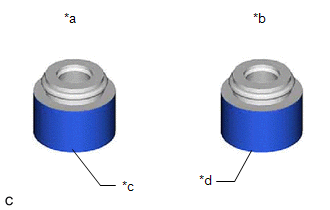
5. INSTALL VALVE STEM OIL SEAL
| (a) Apply a light coat of engine oil to 16 new valve stem oil seals. NOTICE: Make sure to install each valve stem oil seal to the correct side. Installing an intake valve stem oil seal to the exhaust side or installing an exhaust valve stem oil seal to the intake side can cause installation problems later. HINT: The intake valve stem oil seals are gold and the exhaust valve stem oil seals are gray. |
|
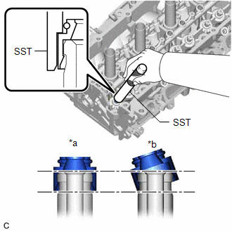
| (b) Using SST, push in the 16 valve stem oil seals. SST: 09201-41020 NOTICE:
|
|
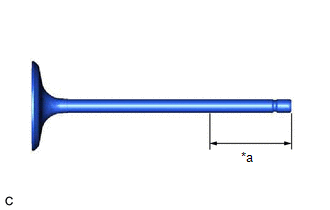
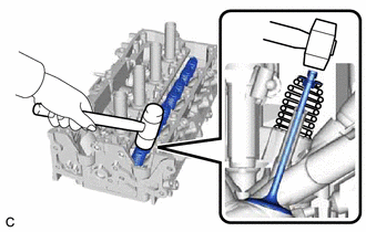
6. INSTALL INTAKE VALVE
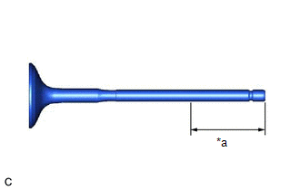
| (a) Sufficiently apply engine oil to the tip area of the intake valve shown in the illustration. |
|
(b) Install the 8 intake valves, 8 compression springs and 8 valve spring retainers to the cylinder head sub-assembly.
NOTICE:
Install the same parts in the same combination to their original locations.
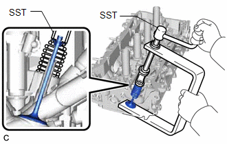
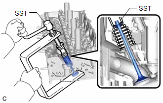
| (c) Using SST, compress each compression spring and install the 8 valve spring retainer locks. SST: 09202-70020 09202-01010 09202-01020 SST: 09202-00021 |
|
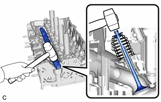
| (d) Using a plastic hammer, lightly tap the valve stem tip to ensure a proper fit. NOTICE:
|
|
7. INSTALL EXHAUST VALVE
| (a) Sufficiently apply engine oil to the tip area of the exhaust valve shown in the illustration. |
|
(b) Install the 8 exhaust valves, 8 compression springs and 8 valve spring retainers to the cylinder head sub-assembly.
NOTICE:
Install the same parts in the same combination to their original locations.
| (c) Using SST, compress each compression spring and install the 8 valve spring retainer locks. SST: 09202-70020 09202-01010 09202-01020 SST: 09202-00021 |
|
| (d) Using a plastic hammer, lightly tap the valve stem tip to ensure a proper fit. NOTICE:
|
|
READ NEXT:
 Repair
REPAIR PROCEDURE 1. REPAIR EXHAUST VALVE SEAT NOTICE:
While repairing the exhaust valve seat, make sure to constantly check the valve seat width and valve seating position.
Release the cutter gra
Drive Belt
ComponentsCOMPONENTS ILLUSTRATION *1 NO. 2 ENGINE UNDER COVER ASSEMBLY *2 V-RIBBED BELT *3 FRONT WHEEL OPENING EXTENSION PAD LH *4 FRONT WHEEL OPENING EXTENSION PAD RH *5 NO
SEE MORE:
Brake Override System
DESCRIPTION When the vehicle is being driven, depressing the accelerator pedal sensor assembly and brake pedal will activate the brake override system to restrict engine output. The conditions for activating the brake override system as well as the items that are controlled are explained below. Act
Left Low Beam Fan Malfunction (B243D,B243E)
DESCRIPTION The headlight ECU sub-assembly operates the low beam fan to cool the headlight LED unit in order to prevent the headlight LED unit from overheating. Illuminates the low beam headlights and continuously operates the low beam fan. The headlight ECU sub-assembly monitors the pulse signals f
