Lexus ES: Replacement
REPLACEMENT
CAUTION / NOTICE / HINT
The necessary procedures (adjustment, calibration, initialization, or registration) that must be performed after parts are removed and installed, or replaced during input shaft type T oil seal removal/installation are shown below.
Necessary Procedure After Parts Removed/Installed/Replaced| Replaced Part or Performed Procedure | Necessary Procedure | Effect/Inoperative Function when Necessary Procedure not Performed | Link |
|---|---|---|---|
| Auxiliary battery terminal is disconnected/reconnected | Perform steering sensor zero point calibration | Lane Control System (for HV Model) | |
| Pre-collision System (for HV Model) | |||
| Parking Support Brake System (for HV Model)* | |||
| Lighting System (for HV Model) | |||
| Memorize steering angle neutral point | Parking Assist Monitor System (for HV Model) | | |
| Panoramic View Monitor System (for HV Model) | | ||
| Initialize power trunk lid system | Power Trunk Lid System (for HV Model) | | |
| Replacement of ECM | Perform Vehicle Identification Number (VIN) registration | MIL illuminates | |
| Inspection After Repair |
| |
| Replacement of inverter with converter assembly | Resolver learning |
| |
| Replacement of hybrid vehicle transaxle assembly |
| ||
| Front wheel alignment adjustment |
|
| |
|
|
| |
| Suspension, tires, etc.*1 | Rear television camera assembly optical axis (Back camera position setting) | Parking Assist Monitor System (for HV Model) | |
| Replacement of front bumper assembly | Front television camera view adjustment | Panoramic View Monitor System (for HV Model) | |
| Suspension, tires, etc.*1 |
| ||
| Replacement of headlight ECU sub-assembly LH |
| Lighting system (for HV Model) | |
| Suspension, tires, etc.*1 | Perform headlight ECU sub-assembly LH initialization*2 |
-
*: When performing learning using the Techstream.
Click here
.gif)
- *1: If the vehicle height has changed due to suspension or tire replacement.
- *2: for LED type turn signal light
CAUTION:
-
Orange wire harnesses and connectors indicate high-voltage circuits. To prevent electric shock, always follow the procedure described in the repair manual.
.png)
Click here
-
To prevent electric shock, wear insulated gloves when working on wire harnesses and components of the high voltage system.
.png)
-
To prevent burns, do not touch the engine, exhaust pipe or other high temperature components while the engine is hot.
.png)
-
To prevent burns, do not touch the engine, exhaust manifold or other high temperature components while the engine is hot.
.png)
-
The engine assembly with transaxle is very heavy. Be sure to follow the procedure described in the repair manual, or the engine lifter may suddenly drop or the engine assembly with transaxle may fall off the engine lifter.
.png)
*a
An Object Exceeding Weight Limit of Engine Lifter
-
The hybrid vehicle transaxle assembly is very heavy. Be sure to follow the procedure described in the repair manual, or the transmission jack may suddenly drop or a part may fall.
.png)
*a
Object Exceeding Weight Limit of Transmission Jack
NOTICE:
- After the engine switch is turned off, the radio receiver assembly records various types of memory and settings. As a result, after turning the engine switch off, make sure to wait at least 85 seconds before disconnecting the cable from the negative (-) battery terminal. (for Audio and Visual System)
- After the engine switch is turned off, the radio receiver assembly records various types of memory and settings. As a result, after turning the engine switch off, make sure to wait at least 85 seconds before disconnecting the cable from the negative (-) battery terminal. (for Navigation System)
PROCEDURE
1. REMOVE HYBRID VEHICLE TRANSAXLE ASSEMBLY
Click here
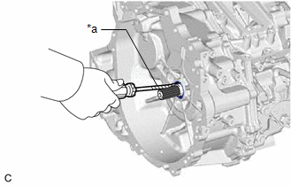
2. REMOVE INPUT SHAFT TYPE T OIL SEAL
| (a) Using a screwdriver with its tip wrapped with protective tape, remove the input shaft type T oil seal from the hybrid vehicle transaxle assembly. NOTICE: Be careful not to damage the input shaft assembly or hybrid vehicle transaxle assembly. |
|
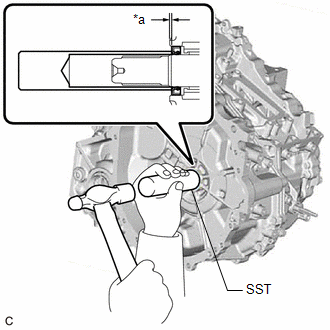
3. INSTALL INPUT SHAFT TYPE T OIL SEAL
(a) Coat the lip of a new input shaft type T oil seal with a small amount of MP grease.
| (b) Using SST and a hammer, install the input shaft type T oil seal to the hybrid vehicle transaxle assembly. SST: 09608-04031 Standard Depth: 1.9 to 2.7 mm (0.0748 to 0.106 in.) NOTICE:
|
|
4. INSTALL HYBRID VEHICLE TRANSAXLE ASSEMBLY
Click here
READ NEXT:
 Components
COMPONENTS ILLUSTRATION *1 MOTOR CABLE *2 CONNECTOR COVER *3 TERMINAL CAP - - Tightening torque for "Major areas involving basic vehicle performance such as moving/turning/s
Installation
INSTALLATION PROCEDURE 1. INSTALL MOTOR CABLE CAUTION: Be sure to wear insulated gloves. (a) Using an insulated tool, install the motor cable to the hybrid vehicle transaxle assembly with the 6 bolts.
SEE MORE:
Removal
REMOVAL CAUTION / NOTICE / HINT The necessary procedures (adjustment, calibration, initialization or registration) that must be performed after parts are removed and installed, or replaced during knock control sensor removal/installation are shown below. Necessary Procedures After Parts Removed/Inst
Brake Switch "A" Signal Compare Failure (P057162)
DESCRIPTION When the brake pedal is depressed, the stop light switch assembly outputs a signal to the ECM. The ECM uses this signal to control cancellation of vehicle speed by the dynamic radar cruise control. When the ECM determines that terminals STP and ST1 of the stop light switch assembly are b
