Lexus ES: Replacement
REPLACEMENT
CAUTION / NOTICE / HINT
The necessary procedures (adjustment, calibration, initialization, or registration) that must be performed after parts are removed and installed, or replaced during rear drive shaft oil seal LH removal/installation are shown below.
Necessary Procedures After Parts Removed/Installed/Replaced| Replaced Part or Performed Procedure | Necessary Procedure | Effect/Inoperative Function when Necessary Procedure not Performed | Link |
|---|---|---|---|
| *1: for LED Type Turn Signal Light | |||
| Rear wheel alignment adjustment |
|
| |
| Suspension, tires, etc. (The vehicle height changes because of suspension or tire replacement) |
|
| |
| Rear television camera assembly optical axis adjustment (Back camera position setting) | Parking Assist Monitor System | | |
| Panoramic View Monitor System | | |
| Perform headlight ECU sub-assembly LH initialization*1 | Lighting System | | |
| Rear height control sensor sub-assembly LH | Perform headlight ECU sub-assembly LH initialization*1 | Lighting System | |
HINT:
- Use the same procedure for the RH side and LH side.
- The following procedure is for the LH side.
PROCEDURE
1. REMOVE REAR DRIVE SHAFT ASSEMBLY LH
Click here .gif)
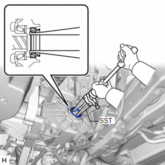
2. REMOVE REAR DRIVE SHAFT OIL SEAL LH
| (a) Using SST, tap out the rear drive shaft oil seal LH. SST: 09308-00010 NOTICE: Be careful not to damage the rear differential carrier sub-assembly. |
|
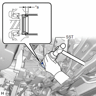
3. INSTALL REAR DRIVE SHAFT OIL SEAL LH
(a) Coat the lip of a new rear drive shaft oil seal LH with MP grease.
| (b) Using SST and a hammer, install the rear drive shaft oil seal LH to the rear differential carrier sub-assembly. SST: 09223-00010 Standard Depth: 6.7 to 7.7 mm (0.264 to 0.303 in.) NOTICE:
|
|
4. INSTALL REAR DRIVE SHAFT ASSEMBLY LH
Click here
READ NEXT:
 Components
COMPONENTS ILLUSTRATION *1 FRONT LOWER BALL JOINT ASSEMBLY *2 STEERING KNUCKLE *3 FRONT AXLE HUB SUB-ASSEMBLY *4 FRONT DISC BRAKE DUST COVER *5 COTTER PIN - - Tigh
Installation
INSTALLATION CAUTION / NOTICE / HINT for HV Model:
When removing or installing the front disc brake caliper assembly, pushing back the disc brake piston may cause a large clearance between the brak
SEE MORE:
Problem Symptoms Table
PROBLEM SYMPTOMS TABLE HINT:
Use the table below to help determine the cause of problem symptoms. If multiple suspected areas are listed, the potential causes of the symptoms are listed in order of probability in the "Suspected Area" column of the table. Check each symptom by checking the suspect
Restraints Occupant Classification System Module Communication Stop Mode
DESCRIPTION Detection Item Symptom Trouble Area Restraints Occupant Classification System Module Communication Stop Mode Any of the following conditions are met:
Communication stop for "Occupant Detection" is indicated on the "Communication Bus Check" screen of the Techstream.
Click
