Lexus ES: Inspection
INSPECTION
PROCEDURE
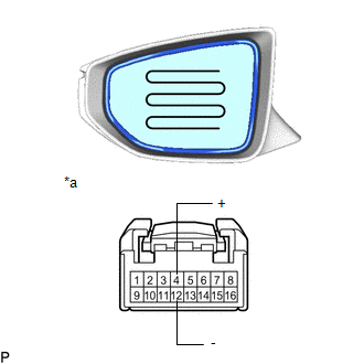
1. INSPECT OUTER REAR VIEW MIRROR ASSEMBLY RH
(a) Check the operation of the mirror surface.
NOTICE:
If the mirror surface is fully turned to the right, left, upward or downward position, the motor slips and produces a clicking noise. This is not a malfunction.
| (1) Disconnect the outer rear view mirror assembly RH connector. |
|
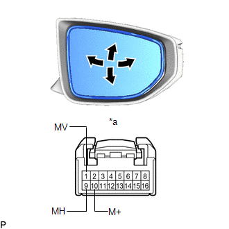
(2) Apply auxiliary battery voltage and check the operation of the mirror surface.
OK:
| Battery Connection | Specified Condition |
|---|---|
| Auxiliary battery positive (+) → Terminal 1 (MV) Auxiliary battery negative (-) → Terminal 10 (M+) | Turns upward |
| Auxiliary battery positive (+) → Terminal 10 (M+) Auxiliary battery negative (-) → Terminal 1 (MV) | Turns downward |
| Auxiliary battery positive (+) → Terminal 9 (MH) Auxiliary battery negative (-) → Terminal 10 (M+) | Turns left |
| Auxiliary battery positive (+) → Terminal 10 (M+) Auxiliary battery negative (-) → Terminal 9 (MH) | Turns right |
If the result is not as specified, replace the outer rear view mirror assembly RH.
(b) Check the operation of the mirror heater.
| (1) Disconnect the outer rear view mirror assembly RH connector. |
|
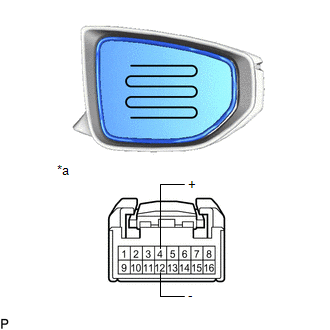
(2) Measure the resistance according to the value(s) in the table below.
Standard Resistance:
| Tester Connection | Condition | Specified Condition |
|---|---|---|
| 4 (+) - 12 (-) | 25°C (77°F) | 3.8 to 5.8 Ω |
If the result is not as specified, replace the outer rear view mirror assembly RH.
(3) Connect a cable from the positive (+) auxiliary battery terminal to terminal 4 and the negative (-) auxiliary battery terminal to terminal 12, then check that the mirror becomes warm.
HINT:
It takes a short time for the mirror to become warm.
OK:
Mirror becomes warm.
If the result is not as specified, replace the outer rear view mirror assembly RH.
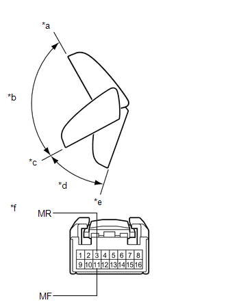
(c) Check the operation of the retractable mirror. (w/ Automatic Retractable Mirror)
NOTICE:
- Disconnect and reconnect the auxiliary battery between each mirror position check.
- The mirror position cannot be changed manually when the auxiliary battery is connected. To change the mirror position manually, the auxiliary battery must be disconnected first.
- If the motor is kept energized, even after each mirror position check, it may lead to a motor malfunction. Make sure to disconnect the auxiliary battery immediately after performing each mirror position check.
| (1) Disconnect the outer rear view mirror assembly RH connector. |
|
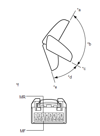
(2) For each position: Disconnect the auxiliary battery, set the mirror position by hand, connect the auxiliary battery, and check the retractable mirror movement.
OK:
| Battery Connection | Condition | Specified Condition |
|---|---|---|
| Auxiliary battery positive (+) → Terminal 3 (MR) Auxiliary battery negative (-) → Terminal 11 (MF) | Forward position (A) | Moves from (A) to (E) |
| Auxiliary battery positive (+) → Terminal 11 (MF) Auxiliary battery negative (-) → Terminal 3 (MR) | Forward position (A) | Does not move |
| Auxiliary battery positive (+) → Terminal 3 (MR) Auxiliary battery negative (-) → Terminal 11 (MF) | Position between forward position (A) and driving position (C) | Moves from (B) to (E) |
| Auxiliary battery positive (+) → Terminal 11 (MF) Auxiliary battery negative (-) → Terminal 3 (MR) | Position between forward position (A) and driving position (C) | Moves from (B) to (A) |
| Auxiliary battery positive (+) → Terminal 3 (MR) Auxiliary battery negative (-) → Terminal 11 (MF) | Driving position (C) | Moves from (C) to (E) |
| Auxiliary battery positive (+) → Terminal 11 (MF) Auxiliary battery negative (-) → Terminal 3 (MR) | Driving position (C) | Does not move |
| Auxiliary battery positive (+) → Terminal 3 (MR) Auxiliary battery negative (-) → Terminal 11 (MF) | Position between driving position (C) and retracted position (E) | Moves from (D) to (E) |
| Auxiliary battery positive (+) → Terminal 11 (MF) Auxiliary battery negative (-) → Terminal 3 (MR) | Position between driving position (C) and retracted position (E) | Moves from (D) to (C) |
| Auxiliary battery positive (+) → Terminal 3 (MR) Auxiliary battery negative (-) → Terminal 11 (MF) | Retracted position (E) | Does not move |
| Auxiliary battery positive (+) → Terminal 11 (MF) Auxiliary battery negative (-) → Terminal 3 (MR) | Retracted position (E) | Moves from (E) to (C) |
If the result is not as specified, replace the outer mirror retractor RH.
2. INSPECT OUTER REAR VIEW MIRROR ASSEMBLY LH
(a) Check the operation of the mirror surface.
NOTICE:
If the mirror surface is fully turned to the right, left, upward or downward position, the motor slips and produces a clicking noise. This is not a malfunction.
| (1) Disconnect the outer rear view mirror assembly LH connector. |
|
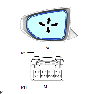
(2) Apply auxiliary battery voltage and check the operation of the mirror surface.
OK:
| Battery Connection | Specified Condition |
|---|---|
| Auxiliary battery positive (+) → Terminal 1 (MV) Auxiliary battery negative (-) → Terminal 10 (M+) | Turns upward |
| Auxiliary battery positive (+) → Terminal 10 (M+) Auxiliary battery negative (-) → Terminal 1 (MV) | Turns downward |
| Auxiliary battery positive (+) → Terminal 9 (MH) Auxiliary battery negative (-) → Terminal 10 (M+) | Turns right |
| Auxiliary battery positive (+) → Terminal 10 (M+) Auxiliary battery negative (-) → Terminal 9 (MH) | Turns left |
If the result is not as specified, replace the outer rear view mirror assembly LH.
(b) Check the operation of the mirror heater.
| (1) Disconnect the outer rear view mirror assembly LH connector. |
|
(2) Measure the resistance according to the value(s) in the table below.
Standard Resistance:
| Tester Connection | Condition | Specified Condition |
|---|---|---|
| 4 (+) - 12 (-) | 25°C (77°F) | 3.8 to 5.8 Ω |
If the result is not as specified, replace the outer rear view mirror assembly LH.
(3) Connect a cable from the positive (+) auxiliary battery terminal to terminal 4 and the negative (-) auxiliary battery terminal to terminal 12, then check that the mirror becomes warm.
HINT:
It takes a short time for the mirror to become warm.
OK:
Mirror becomes warm.
If the result is not as specified, replace the outer rear view mirror assembly LH.
(c) Check the operation of the retractable mirror. (w/ Automatic Retractable Mirror)
NOTICE:
- Disconnect and reconnect the auxiliary battery between each mirror position check.
- The mirror position cannot be changed manually when the auxiliary battery is connected. To change the mirror position manually, the auxiliary battery must be disconnected first.
- If the motor is kept energized, even after each mirror position check, it may lead to a motor malfunction. Make sure to disconnect the auxiliary battery immediately after performing each mirror position check.
| (1) Disconnect the outer rear view mirror assembly LH connector. |
|
(2) For each position: Disconnect the auxiliary battery, set the mirror position by hand, connect the auxiliary battery, and check the retractable mirror movement.
OK:
| Battery Connection | Condition | Specified Condition |
|---|---|---|
| Auxiliary battery positive (+) → Terminal 3 (MR) Auxiliary battery negative (-) → Terminal 11 (MF) | Forward position (A) | Moves from (A) to (E) |
| Auxiliary battery positive (+) → Terminal 11 (MF) Auxiliary battery negative (-) → Terminal 3 (MR) | Forward position (A) | Does not move |
| Auxiliary battery positive (+) → Terminal 3 (MR) Auxiliary battery negative (-) → Terminal 11 (MF) | Position between forward position (A) and driving position (C) | Moves from (B) to (E) |
| Auxiliary battery positive (+) → Terminal 11 (MF) Auxiliary battery negative (-) → Terminal 3 (MR) | Position between forward position (A) and driving position (C) | Moves from (B) to (A) |
| Auxiliary battery positive (+) → Terminal 3 (MR) Auxiliary battery negative (-) → Terminal 11 (MF) | Driving position (C) | Moves from (C) to (E) |
| Auxiliary battery positive (+) → Terminal 11 (MF) Auxiliary battery negative (-) → Terminal 3 (MR) | Driving position (C) | Does not move |
| Auxiliary battery positive (+) → Terminal 3 (MR) Auxiliary battery negative (-) → Terminal 11 (MF) | Position between driving position (C) and retracted position (E) | Moves from (D) to (E) |
| Auxiliary battery positive (+) → Terminal 11 (MF) Auxiliary battery negative (-) → Terminal 3 (MR) | Position between driving position (C) and retracted position (E) | Moves from (D) to (C) |
| Auxiliary battery positive (+) → Terminal 3 (MR) Auxiliary battery negative (-) → Terminal 11 (MF) | Retracted position (E) | Does not move |
| Auxiliary battery positive (+) → Terminal 11 (MF) Auxiliary battery negative (-) → Terminal 3 (MR) | Retracted position (E) | Moves from (E) to (C) |
If the result is not as specified, replace the outer mirror retractor LH.
READ NEXT:
 Reassembly
REASSEMBLY CAUTION / NOTICE / HINT HINT:
Use the same procedure for the RH side and LH side.
The following procedure is for the LH side.
PROCEDURE 1. INSTALL VISOR COVER ASSEMBLY Click here
Installation
INSTALLATION CAUTION / NOTICE / HINT HINT:
Use the same procedure for the RH side and LH side.
The following procedure is for the LH side.
PROCEDURE 1. INSTALL OUTER REAR VIEW MIRROR ASSEMBLY
SEE MORE:
Mass or Volume Air Flow Sensor "A" Circuit Short to Battery (P010012,P010014)
DESCRIPTION The mass air flow meter sub-assembly is a sensor that measures the intake air volume using the following built-in components:
By-pass duct (allows some of the intake air to flow past a silicon chip sensor)
Silicon chip sensor (uses a heater control bridge circuit and temperature sen
Components
COMPONENTS ILLUSTRATION *A w/o Headup Display *B w/ Headup Display *1 COWL SIDE TRIM BOARD LH *2 FRONT DOOR OPENING TRIM COVER LH *3 FRONT DOOR SCUFF PLATE LH *4 HAZARD WARNING SIGNAL SWITCH ASSEMBLY *5 INSTRUMENT CLUSTER FINISH PANEL SUB-ASSEMBLY *6 INSTRUMEN
