Lexus ES: Removal
REMOVAL
CAUTION / NOTICE / HINT
The necessary procedures (adjustment, calibration, initialization or registration) that must be performed after parts are removed and installed, or replaced during rear height control sensor sub-assembly LH removal/installation are shown below.
Necessary Procedure After Parts Removed/Installed/Replaced (for HV Model)| Replaced Part or Performed Procedure | Necessary Procedure | Effect/Inoperative Function When Necessary Procedures are not Performed | Link |
|---|---|---|---|
| *1: for LED Type Turn Signal Light | |||
| Rear height control sensor sub-assembly LH | Perform headlight ECU sub-assembly LH initialization*1 | Lighting system (for HV Model) | |
| Replaced Part or Performed Procedure | Necessary Procedure | Effect/Inoperative Function when Necessary Procedure not Performed | Link |
|---|---|---|---|
| *1: for LED Type Turn Signal Light | |||
| Rear height control sensor sub-assembly LH | Perform headlight ECU sub-assembly LH initialization*1 | Lighting System (for Gasoline Model) | |
PROCEDURE
1. REMOVE REAR WHEEL (for LH Side)
Click here .gif)
2. REMOVE REAR HEIGHT CONTROL SENSOR SUB-ASSEMBLY LH
NOTICE:
If the rear height control sensor sub-assembly LH has been struck or dropped, replace it with a new one.
(a) for 2WD:
(1) Disconnect the connector.
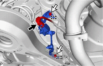
.png) | Connector |
.png) | Bolt |
(2) Remove the 2 bolts.
(3) Disengage the 2 guides to remove the rear height control sensor sub-assembly LH.
(b) for AWD:
(1) Disconnect the connector.
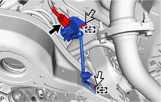
| | Connector |
| | Bolt |
 | Nut |
(2) Remove the bolt and nut.
(3) Disengage the 2 guides to remove the rear height control sensor sub-assembly LH.
READ NEXT:
 Inspection
INSPECTION PROCEDURE 1. INSPECT REAR HEIGHT CONTROL SENSOR SUB-ASSEMBLY LH (for 2WD) (a) Preparation for check (1) Confirm the standard, high and low positions of the link that will be used in the fol
Installation
INSTALLATION PROCEDURE 1. INSTALL REAR HEIGHT CONTROL SENSOR SUB-ASSEMBLY LH NOTICE: If the rear height control sensor sub-assembly LH has been struck or dropped, replace it with a new one. (a) for 2W
High Mounted Stop Light Assembly
ComponentsCOMPONENTS ILLUSTRATION *1 CENTER STOP LIGHT SET - - RemovalREMOVAL PROCEDURE 1. REMOVE CENTER STOP LIGHT SET (a) Disengage the 4 guides as shown in the illustration. D
SEE MORE:
Disassembly
DISASSEMBLY CAUTION / NOTICE / HINT HINT:
Use the same procedure for the RH side and LH side.
The following procedure is for the LH side.
PROCEDURE 1. REMOVE REAR LIGHT GASKET (a) Remove the rear light gasket. NOTICE:
Be sure to remove all traces of the old rear light gasket from the
Customize Parameters
CUSTOMIZE PARAMETERS CUSTOMIZE BLIND SPOT MONITOR SYSTEM (a) Customizing with the Techstream NOTICE:
When the customer requests a change in a function, first make sure that the function can be customized.
Be sure to make a note of the current settings before customizing.
When troubleshooting
