Lexus ES: Removal
REMOVAL
CAUTION / NOTICE / HINT
The necessary procedures (adjustment, calibration, initialization, or registration) that must be performed after parts are removed and installed, or replaced during rear bumper assembly removal/installation are shown below.
Necessary Procedure After Parts Removed/Installed/Replaced| Replaced Part or Performed Procedure | Necessary Procedure | Effect/Inoperative Function When Necessary Procedures are not Performed | Link |
|---|---|---|---|
|
*: When performing learning using the Techstream.
Click here | |||
| Disconnect cable from negative battery terminal | Perform steering sensor zero point calibration | Lane Control System (for Gasoline Model) | |
| Pre-collision System (for Gasoline Model) | |||
| Parking Support Brake System (for Gasoline Model)* | |||
| Lighting System (for Gasoline Model) | |||
| Memorize steering angle neutral point | Parking Assist Monitor System (for Gasoline Model) | | |
| Panoramic View Monitor System (for Gasoline Model) | | ||
| Initialize power trunk lid system | Power Trunk Lid System (for Gasoline Model) | | |
| Rear bumper assembly |
|
| |
NOTICE:
- After the engine switch is turned off, the radio receiver assembly records various types of memory and settings. As a result, after turning the engine switch off, make sure to wait at least 85 seconds before disconnecting the cable from the negative (-) battery terminal. (for Audio and Visual System)
- After the engine switch is turned off, the radio receiver assembly records various types of memory and settings. As a result, after turning the engine switch off, make sure to wait at least 85 seconds before disconnecting the cable from the negative (-) battery terminal. (for Navigation System)
HINT:
If the rear bumper assembly is damaged, there is a possibility that the installation area of the blind spot monitor sensor may be deformed and the blind spot monitor system may not operate correctly. Visually inspect the blind spot monitor sensor installation area (vehicle body, stud bolts) to make sure it is not damaged.
Click here .gif)
If damage is found in the visual inspection, check the installation condition of the blind spot monitor sensor, and adjust the installation position of the blind spot monitor sensor as necessary.
PROCEDURE
1. PRECAUTION (w/ Hands Free Power Trunk Lid)
NOTICE:
After turning the engine switch off, waiting time may be required before disconnecting the cable from the negative (-) battery terminal. Therefore, make sure to read the disconnecting the cable from the negative (-) battery terminal notices before proceeding with work.
2. DISCONNECT CABLE FROM NEGATIVE BATTERY TERMINAL (w/ Hands Free Power Trunk Lid)
Click here
3. REMOVE REAR COMBINATION LIGHT COVER LH
Click here
4. REMOVE REAR COMBINATION LIGHT COVER RH
HINT:
Use the same procedure as for the LH side.
5. REMOVE REAR BUMPER ASSEMBLY
(a) Apply protective tape around the rear bumper assembly as shown in the illustration.
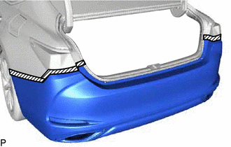
.png) | Protective Tape |
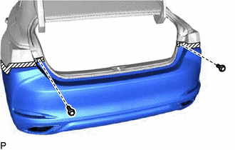
| (b) Remove the 2 screws. |
|
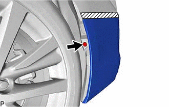
| (c) Remove the clip. HINT: Use the same procedure for the RH side and LH side. |
|
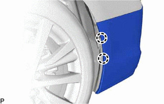
| (d) Disengage the 2 claws. HINT: Use the same procedure for the RH side and LH side. |
|
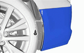
| (e) Remove the screw. HINT: Use the same procedure for the RH side and LH side. |
|
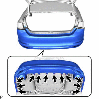
| (f) Remove the 12 clips. |
|
(g) Disengage the 6 claws as shown in the illustration.
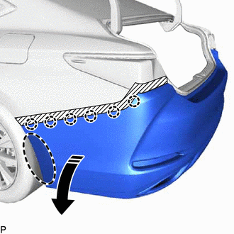
.png) | Place Hand Here |
.png) | Remove in this Direction |
HINT:
Use the same procedure for the RH side and LH side.
(h) Disengage the 6 claws to remove the rear bumper assembly as shown in the illustration.
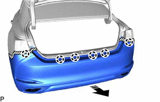
| | Remove in this Direction |
(i) w/ Wire Harness:
(1) Disconnect the connector to remove the rear bumper assembly.
READ NEXT:
 Disassembly
DISASSEMBLY PROCEDURE 1. REMOVE KICK DOOR CONTROL SENSOR WITH BRACKET (w/ Hands Free Power Trunk Lid) Click here 2. REMOVE REAR CENTER ULTRASONIC SENSOR (w/ Parking Support Alert System) Click here
Reassembly
REASSEMBLY PROCEDURE 1. INSTALL REAR BUMPER REINFORCEMENT Click here 2. INSTALL REAR BUMPER PROTECTOR INSERT LH Click here 3. INSTALL REAR BUMPER PROTECTOR INSERT RH HINT: Use the same procedure a
Installation
INSTALLATION PROCEDURE 1. INSTALL REAR BUMPER ASSEMBLY (a) w/ Wire Harness: (1) Connect the connector. (b) Engage the 6 claws as shown in the illustration. Install in this Direction (c) Enga
SEE MORE:
Barometric Pressure Sensor "A" Circuit Short to Ground (P222611,P222615)
DESCRIPTION The atmospheric pressure sensor is built into the ECM. The ECM provides optimal control in response to atmospheric pressure fluctuations. DTC No. Detection Item DTC Detection Condition Trouble Area MIL Memory Note P222611 Barometric Pressure Sensor "A" Circuit Short
Installation
INSTALLATION PROCEDURE 1. INSTALL NO. 2 ECM BRACKET (a) Install the No. 2 ECM bracket to the ECM with the 2 screws. Torque: 4.5 N·m {46 kgf·cm, 40 in·lbf} 2. INSTALL NO. 1 ECM BRACKET (a) Install the No. 1 ECM bracket to the ECM with the 2 screws. Torque: 4.5 N·m {46 kgf·cm, 40 in·lbf} 3. IN
