Lexus ES: Installation
INSTALLATION
PROCEDURE
1. INSTALL NO. 2 ECM BRACKET
(a) Install the No. 2 ECM bracket to the ECM with the 2 screws.
Torque:
4.5 N·m {46 kgf·cm, 40 in·lbf}
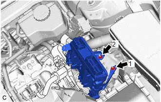
2. INSTALL NO. 1 ECM BRACKET
(a) Install the No. 1 ECM bracket to the ECM with the 2 screws.
Torque:
4.5 N·m {46 kgf·cm, 40 in·lbf}
3. INSTALL ECM
| (a) Install the ECM with the 2 nuts in the order shown in the illustration. Torque: 8.0 N·m {82 kgf·cm, 71 in·lbf} NOTICE: If the ECM has been struck or dropped, replace it. |
|
| (b) Engage the clamp. |
|
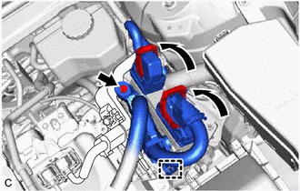
(c) Install the engine wire to the No. 2 ECM bracket with the bolt.
Torque:
10 N·m {102 kgf·cm, 7 ft·lbf}
(d) Connect the 2 ECM connectors and rotate the 2 levers to lock them.
NOTICE:
- When connecting the ECM connectors, make sure that the connecting parts of the ECM connectors are free of dirt, water and other foreign matter.
- Be sure to securely connect the ECM connectors.
4. CONNECT CABLE TO NEGATIVE AUXILIARY BATTERY TERMINAL
Click here .gif)
5. PERFORM INITIALIZATION
Click here
READ NEXT:
 Components
COMPONENTS ILLUSTRATION *1 COOL AIR INTAKE DUCT SEAL *2 ENGINE COOLANT TEMPERATURE SENSOR *3 INLET AIR CLEANER ASSEMBLY *4 NO. 2 ENGINE COOLANT TEMPERATURE SENSOR N*m (kgf*c
Removal
REMOVAL CAUTION / NOTICE / HINT The necessary procedures (adjustment, calibration, initialization, or registration) that must be performed after parts are removed and installed, or replaced during eng
SEE MORE:
DC/DC Converter Temperature Sensor "B" Circuit Voltage Out of Range (P0C3D1C)
DTC SUMMARY MALFUNCTION DESCRIPTION These DTCs indicate that the boost converter temperature sensor (lower) value is abnormal. The cause of this malfunction may be one of the following: Internal inverter malfunction
Inverter with converter assembly internal circuit malfunction
Hybrid cooling
Starter Relay Circuit Short to Battery (P061512)
DESCRIPTION While the engine is being cranked, battery voltage is applied to terminal STA of the ECM. If the ECM detects the starter control (STA) signal while the vehicle is being driven, it determines that there is a malfunction in the STA circuit. The ECM then illuminates the MIL and stores this
