Lexus ES: Removal
REMOVAL
CAUTION / NOTICE / HINT
The necessary procedures (adjustment, calibration, initialization, or registration) that must be performed after parts are removed and installed, or replaced during luggage door hinge torsion bar removal/installation are shown below.
Necessary Procedure After Parts Removed/Installed/Replaced (for Gasoline Model)| Replaced Part or Performed Procedure | Necessary Procedure | Effect/Inoperative Function When Necessary Procedures are not Performed | Link |
|---|---|---|---|
| Luggage closer motor assembly (w/ Power Trunk Lid System) | Initialize power trunk lid system | Power Trunk Lid System | |
| Replaced Part or Performed Procedure | Necessary Procedure | Effect/Inoperative Function When Necessary Procedures are not Performed | Link |
|---|---|---|---|
| Luggage closer motor assembly (w/ Power Trunk Lid System) | Initialize power trunk lid system | Power Trunk Lid System | |
NOTICE:
After installing the luggage door hinge torsion bar, use your hand to open and close the luggage door. Make sure the luggage door can open and close smoothly.
PROCEDURE
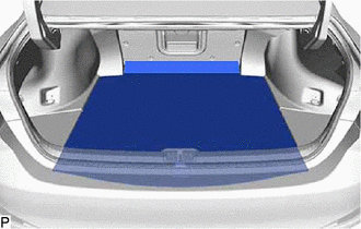
1. REMOVE LUGGAGE COMPARTMENT FLOOR MAT
| (a) Remove the luggage compartment floor mat. |
|
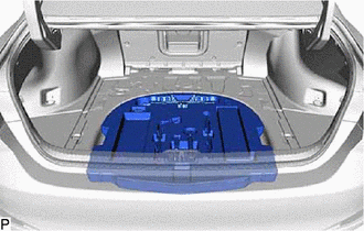
2. REMOVE SPARE WHEEL COVER TRAY
| (a) Remove the spare wheel cover tray. |
|
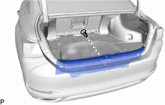
3. REMOVE REAR FLOOR FINISH PLATE
| (a) Remove the bolt. HINT: Use the same procedure for the RH side and LH side. |
|
(b) Disengage the guide to remove the luggage hold belt striker assembly.
HINT:
Use the same procedure for the RH side and LH side.
| (c) Remove the clip. |
|
(d) Disengage the 6 clips to remove the rear floor finish plate as shown in the illustration.
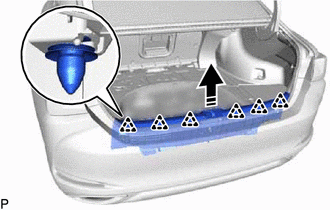
.png) | Remove in this Direction |
4. REMOVE LUGGAGE COMPARTMENT TRIM COVER RH
| (a) Disengage the 2 claws to remove the luggage compartment trim cover RH. |
|
5. REMOVE LUGGAGE COMPARTMENT TRIM COVER LH
| (a) Disengage the 2 claws to remove the luggage compartment trim cover LH. |
|
6. REMOVE LUGGAGE COMPARTMENT TRIM INNER COVER RH
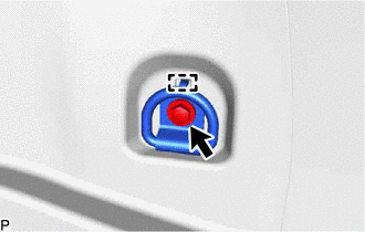
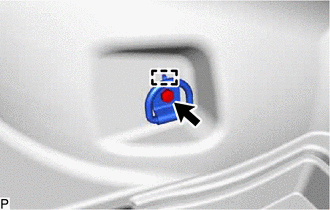
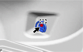
(a) Disengage the 2 claws and remove the rope hook as shown in the illustration.
.png) | Push |
| | Remove in this Direction |
| (b) Remove the bolt. |
|
(c) Disengage the guide to remove the luggage hold belt striker assembly.
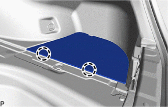
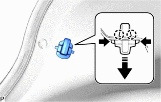
| (d) Using a clip remover, remove the 4 clips. |
|
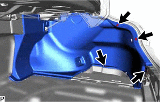
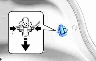
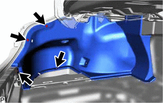
(e) Disengage each fastener and remove the luggage compartment inner trim cover RH.
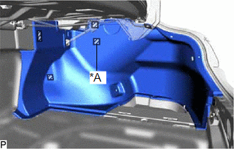
| *A | w/ Power Trunk Lid System |
.png) | Fastener |
7. REMOVE LUGGAGE COMPARTMENT TRIM INNER COVER LH
(a) Disengage the 2 claws and remove the rope hook as shown in the illustration.
| | Push |
| | Remove in this Direction |
| (b) Remove the bolt. |
|
(c) Disengage the guide to remove the luggage hold belt striker assembly.
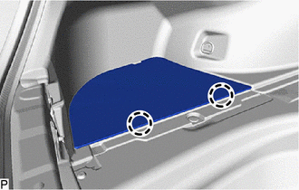
| (d) Using a clip remover, remove the 4 clips. |
|
(e) Disengage the 4 fasteners and remove the luggage compartment inner trim cover LH.
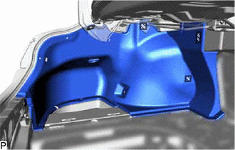
| | Fastener |
8. REMOVE LUGGAGE LOCK CONTROL CABLE PLATE (w/ Power Trunk Lid System)
Click here .gif)
9. REMOVE SWITCH BEZEL (w/ Power Trunk Lid System)
Click here
10. REMOVE LUGGAGE COMPARTMENT DOOR COVER (w/ Power Trunk Lid System)
Click here
11. REMOVE LUGGAGE COMPARTMENT DOOR HINGE COVER RH (w/ Power Trunk Lid System)
HINT:
Use the same procedure as for the LH side.
Click here
12. REMOVE LUGGAGE CLOSER MOTOR ASSEMBLY (w/ Power Trunk Lid System)
Click here
13. REMOVE LUGGAGE DOOR HINGE TORSION BAR LH
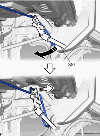
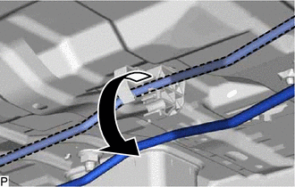
(a) Using SST, disconnect the luggage door hinge torsion bar LH from the luggage door hinge and the left side of the vehicle body as shown in the illustration.
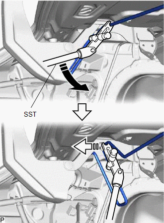
| | Remove in this Direction (1) |
.png) | Remove in this Direction (2) |
SST: 09804-24010
09804-04010
09804-04040
09804-04030
09804-04020
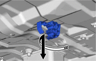
| (b) Disengage the 2 claws as shown in the illustration. |
|
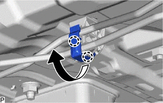
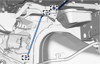
| (c) Disconnect the luggage door hinge torsion bar LH from the luggage compartment door torsion bar support as shown in the illustration. |
|
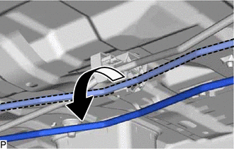
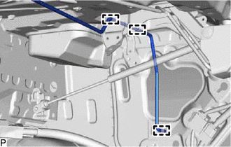
| (d) Disengage the 3 guides and remove the luggage door hinge torsion bar LH. |
|
14. REMOVE LUGGAGE DOOR HINGE TORSION BAR RH
(a) Using SST, disconnect the luggage door hinge torsion bar RH from the luggage door hinge and the right side of the vehicle body as shown in the illustration.
| | Remove in this Direction (1) |
| | Remove in this Direction (2) |
SST: 09804-24010
09804-04010
09804-04020
09804-04030
09804-04040
| (b) Disconnect the luggage door hinge torsion bar RH from the luggage compartment door torsion bar support as shown in the illustration. |
|
| (c) Disengage the 3 guides and remove the luggage door hinge torsion bar RH. |
|
15. REMOVE LUGGAGE COMPARTMENT DOOR TORSION BAR SUPPORT
(a) Remove the luggage compartment door torsion bar support as shown in the illustration.
| | Remove in this Direction |
NOTICE:
Make sure to replace the luggage compartment door torsion bar support with a new one.
READ NEXT:
 Installation
INSTALLATION CAUTION / NOTICE / HINT NOTICE: After installing the luggage door hinge torsion bar, use your hand to open and close the luggage door. Make sure the luggage door can open and close smooth
Precaution
PRECAUTION PRECAUTIONS FOR INSPECTING POWER SOURCE FOR MAIN BODY ECU (MULTIPLEX NETWORK BODY ECU) NOTICE: When disconnecting the cable from the negative (-) battery terminal, initialize the following
SEE MORE:
Motor Resolver Circuit
DESCRIPTION The cause of this malfunction may be the motor resolver. Check the motor resolver internal resistance and the connection condition from the inverter to the resolver. Related Parts Check Area Inspection Wire harness and connector between the inverter and motor resolver Check fo
Problem Symptoms Table
PROBLEM SYMPTOMS TABLE If DTCs are not output but the malfunction persists, use the following table to determine which circuits to inspect for each problem symptom. HINT: Refer to each inspection procedure for related problem symptoms. Electronically Controlled Brake System Symptom Suspected Ar
