Lexus ES: Removal
REMOVAL
CAUTION / NOTICE / HINT
The necessary procedures (adjustment, calibration, initialization, or registration) that must be performed after parts are removed and installed, or replaced during telephone antenna assembly removal/installation are shown below.
Necessary Procedure After Parts Removed/Installed/Replaced (for HV Model)| Replaced Part or Performed Procedure | Necessary Procedures | Effect/Inoperative Function When Necessary Procedures are not Performed | Link |
|---|---|---|---|
|
*: When performing learning using the Techstream.
Click here | |||
| Disconnect cable from negative auxiliary battery terminal | Perform steering sensor zero point calibration | Lane Control System | |
| Pre-collision System | |||
| Parking Support Brake System* | |||
| Lighting System | |||
| Memorize steering angle neutral point | Parking Assist Monitor System | | |
| Panoramic View Monitor System | | ||
| Initialize power trunk lid system | Power Trunk Lid System | | |
| Removal/installation of the front passenger seat | Zero point calibration (Occupant Classification System) |
| |
CAUTION:
Some of these service operations affect the SRS airbag system. Read the precautionary notices concerning the SRS airbag system before servicing.
.png)
Click here .gif)
NOTICE:
- After the power switch is turned off, the radio receiver assembly records various types of memory and settings. As a result, after turning the power switch off, make sure to wait at least 85 seconds before disconnecting the cable from the negative (-) auxiliary battery terminal. (for Audio and Visual System)
- After the power switch is turned off, the radio receiver assembly records various types of memory and settings. As a result, after turning the power switch off, make sure to wait at least 85 seconds before disconnecting the cable from the negative (-) auxiliary battery terminal. (for Navigation System)
| Replaced Part or Performed Procedure | Necessary Procedures | Effect/Inoperative Function When Necessary Procedures are not Performed | Link |
|---|---|---|---|
|
*: When performing learning using the Techstream.
Click here | |||
| Disconnect cable from negative battery terminal | Perform steering sensor zero point calibration | Lane Control System | |
| Pre-collision System | |||
| Parking Support Brake System* | |||
| Lighting System | |||
| Memorize steering angle neutral point | Parking Assist Monitor System | | |
| Panoramic View Monitor System | | ||
| Initialize power trunk lid system | Power Trunk Lid System | | |
| Removal/installation of the front passenger seat | Zero point calibration (Occupant Classification System) |
| |
CAUTION:
Some of these service operations affect the SRS airbag system. Read the precautionary notices concerning the SRS airbag system before servicing.
Click here
NOTICE:
- After the engine switch is turned off, the radio receiver assembly records various types of memory and settings. As a result, after turning the engine switch off, make sure to wait at least 85 seconds before disconnecting the cable from the negative (-) battery terminal. (for Audio and Visual System)
- After the engine switch is turned off, the radio receiver assembly records various types of memory and settings. As a result, after turning the engine switch off, make sure to wait at least 85 seconds before disconnecting the cable from the negative (-) battery terminal. (for Navigation System)
PROCEDURE
1. REMOVE ROOF HEADLINING ASSEMBLY
Click here
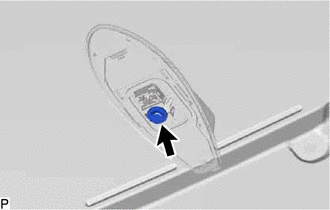
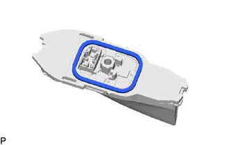
2. REMOVE TELEPHONE ANTENNA ASSEMBLY WITH COVER (for Moon Roof)
| (a) Disconnect the connector. |
|

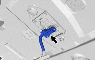
| (b) Remove the bolt. |
|
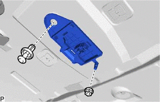
(c) Remove the washer and holder as shown in the illustration.
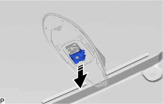
.png) | Remove in this Direction |
(d) Remove the telephone antenna assembly with cover as shown in the illustration.
| | Remove in this Direction |
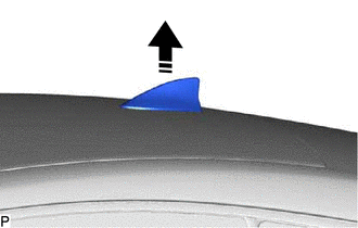
3. REMOVE TELEPHONE ANTENNA ASSEMBLY (for Moon Roof)
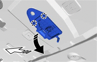
(a) Pull the telephone antenna assembly in the direction indicated by the arrow (1) shown in the illustration to disengage the 3 claws and 2 guides.
| | Remove in this Direction (1) |
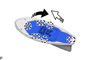
.png) | Remove in this Direction (2) |
(b) Pull the telephone antenna assembly in the direction indicated by the arrow (2) shown in the illustration to disengage the guide and remove the telephone antenna assembly.
(c) When reusing the telephone antenna assembly:
| (1) Remove the seal. |
|
4. REMOVE TELEPHONE ANTENNA ASSEMBLY (for Panoramic Moon Roof)
| (a) Disconnect the connector. |
|
| (b) Remove the nut and clip. |
|
(c) Disengage the 2 claws and remove the telephone antenna assembly as shown in the illustration.
| | Remove in this Direction (1) |
| | Remove in this Direction (2) |
READ NEXT:
 Stereo Component Amplifier
ComponentsCOMPONENTS ILLUSTRATION *1 AUDIO AMPLIFIER COVER *2 STEREO COMPONENT AMPLIFIER ASSEMBLY WITH BRACKET ILLUSTRATION *A for 10 Speakers *B for 17 Speakers *1 NO. 1
Components
COMPONENTS ILLUSTRATION *1 CENTER INSTRUMENT CLUSTER FINISH PANEL SUB-ASSEMBLY *2 INSTRUMENT PANEL FINISH PANEL END LH *3 INSTRUMENT PANEL FINISH PANEL END RH *4 NO. 1 STEREO JACK
SEE MORE:
Emergency Call Switch Illumination Circuit
WIRING DIAGRAM CAUTION / NOTICE / HINT NOTICE:
Depending on the parts that are replaced during vehicle inspection or maintenance, performing initialization, registration or calibration may be needed. Refer to Precaution for Safety Connect System.
Click here
Inspect the fuses for circuits re
Check Bus 3 Line for Short to GND
DESCRIPTION There may be a short circuit between one of the CAN bus lines and GND when there is no resistance between terminal 6 (CA3H) of the central gateway ECU (network gateway ECU) and terminal 4 (CG) of the DLC3, or terminal 21 (CA3L) of the central gateway ECU (network gateway ECU) and termina
