Lexus ES: Remote Engine Starter does not Operate
WIRING DIAGRAM
CAUTION / NOTICE / HINT
NOTICE:
Before replacing the DCM (telematics transceiver), refer to Registration.
Click here .gif)
PROCEDURE
| 1. | CHECK SMART KEY SYSTEM (for Start Function) |
(a) Check that the engine can be started by pressing the engine switch.
| Result | Proceed to |
|---|---|
| Engine can be started. | A |
| Engine cannot be started. | B |
| B | .gif) | GO TO SMART KEY SYSTEM (for Start Function) |
|
.gif)
| 2. | REGISTRATION |
HINT:
If registration is not performed after replacing any of the following parts, the remote engine start and stop will not be available.- Certification ECU (smart key ECU assembly)
- DCM (telematics transceiver)
(a) Perform remote engine start and stop registration.
Click here
(b) Check if the problem symptom recurs.
| Result | Proceed to |
|---|---|
| System does not return to normal. | A |
| System returns to normal. | B |
| B | | END |
|
| 3. | CHECK DTC |
(a) Clear the DTCs.
Body Electrical > Smart Key > Clear DTCs(b) Check for DTCs.
Body Electrical > Smart Key > Trouble Codes| Result | Proceed to |
|---|---|
| DTC B2285 is not output. | A |
| DTC B2285 is output. | B |
| B | | GO TO DTC B2285 |
|
| 4. | CHECK DCM (TELEMATICS TRANSCEIVER) |
| (a) Disconnect the DCM (telematics transceiver) connector. |
|
(b) Measure the voltage according to the value(s) in the table below.
Standard Voltage:
| Tester Connection | Condition | Specified Condition |
|---|---|---|
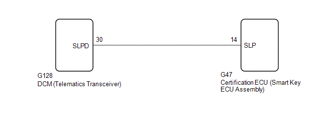
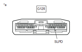
| G128-30 (SLPD) - Body ground | Steering locked | 11 to 14 V |
| Steering unlocked | Below 1.5 V |
HINT:
The steering locks when any door is opened with the shift lever in P and the engine switch off. The steering unlocks when the engine switch is turned on (ACC).
| OK | | REPLACE DCM (TELEMATICS TRANSCEIVER) |
|
| 5. | CHECK HARNESS AND CONNECTOR (DCM [TELEMATICS TRANSCEIVER] - CERTIFICATION ECU [SMART KEY ECU ASSEMBLY]) |
(a) Disconnect the G128 DCM (telematics transceiver) connector.
(b) Disconnect the G47 certification ECU (smart key ECU assembly) connector.
(c) Measure the resistance according to the value(s) in the table below.
Standard Resistance:
| Tester Connection | Condition | Specified Condition |
|---|---|---|
| G128-30 (SLPD) - G47-14 (SLP) | Always | Below 1 Ω |
| OK | | REPLACE CERTIFICATION ECU (SMART KEY ECU ASSEMBLY) |
| NG | | REPAIR OR REPLACE HARNESS OR CONNECTOR |
READ NEXT:
 Remote Service Malfunction
PROCEDURE 1. CHECK CAN COMMUNICATION SYSTEM (a) Connect the Techstream to the DLC3. (b) Turn the engine switch on (IG). (c) Turn the Techstream on. (d) Enter the following menus: Bus Check. C
System Description
SYSTEM DESCRIPTION OUTLINE (a) Lexus Enform Remote, which enables the user to check the vehicle status and operate the vehicle from a remote location, is used. (b) Lexus Enform Remote is available by
System Diagram
SYSTEM DIAGRAM
SEE MORE:
Camshaft Position "A" - Timing Over-Advanced or System Performance Bank 1 Mechanical Failure (P001107,P002107)
DESCRIPTION Refer to DTC P001013. Click here DTC No. Detection Item DTC Detection Condition Trouble Area MIL Memory Note P001107 Camshaft Position "A" - Timing Over-Advanced or System Performance Bank 1 Mechanical Failure 10° CA or greater camshaft timing gear assembly (ban
Rear Window Defogger System does not Operate
DESCRIPTION When the rear window defogger switch on the air conditioning control assembly is pressed, the operation signal is transmitted to the air conditioning amplifier assembly via LIN communication. When the air conditioning amplifier assembly receives the signal, it turns on the DEF relay to o
