Lexus ES: Removal
REMOVAL
CAUTION / NOTICE / HINT
The necessary procedures (adjustment, calibration, initialization, or registration) that must be performed after parts are removed and installed, or replaced during rear upper control arm assembly removal/installation are shown below.
Necessary Procedures After Parts Removed/Installed/Replaced (for HV Model:)| Replaced Part or Performed Procedure | Necessary Procedure | Effect/Inoperative Function when Necessary Procedure not Performed | Link |
|---|---|---|---|
| *1: for LED type turn signal light | |||
| Suspension, tires, etc. (The vehicle height changes because of suspension or tire replacement.) |
|
| |
| Rear television camera assembly optical axis adjustment (Back camera position setting) | Parking Assist Monitor System | | |
| Panoramic View Monitor System | | |
| Perform headlight ECU sub-assembly LH initialization*1 | Lighting System | | |
| Rear height control sensor sub-assembly LH | Perform headlight ECU sub-assembly LH initialization*1 | Lighting System | |
| Rear wheel alignment adjustment |
|
| |
| Gas leak from exhaust system is repaired | Inspection After Repair |
| |
| Replaced Part or Performed Procedure | Necessary Procedure | Effect/Inoperative Function when Necessary Procedure not Performed | Link |
|---|---|---|---|
| *1: for LED type turn signal light | |||
| Suspension, tires, etc. (The vehicle height changes because of suspension or tire replacement.) |
|
| |
| Rear television camera assembly optical axis adjustment (Back camera position setting) | Parking Assist Monitor System | | |
| Panoramic View Monitor System | | |
| Perform headlight ECU sub-assembly LH initialization*1 | Lighting System | | |
| Rear height control sensor sub-assembly LH | Perform headlight ECU sub-assembly LH initialization*1 | Lighting System | |
| Rear wheel alignment adjustment |
|
| |
| Gas leak from exhaust system is repaired | Inspection After Repair |
| |
CAUTION:
To prevent burns, do not touch the engine, exhaust pipe or other high temperature components while the engine is hot.
.png)
PROCEDURE
1. REMOVE REAR SUSPENSION MEMBER SUB-ASSEMBLY
Click here .gif)
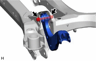
2. REMOVE REAR UPPER CONTROL ARM ASSEMBLY LH
| (a) Remove the bolt, nut and rear upper control arm assembly LH from the rear suspension member sub-assembly. NOTICE: Because the nut has its own stopper, do not turn the nut. Loosen the bolt with the nut secured. |
|
3. REMOVE REAR UPPER CONTROL ARM ASSEMBLY RH
HINT:
Perform the same procedure as for the LH side.
READ NEXT:
 Installation
INSTALLATION PROCEDURE 1. INSTALL REAR UPPER CONTROL ARM ASSEMBLY LH (for 2WD) (a) Temporarily install the rear upper control arm assembly LH to the rear suspension member sub-assembly with the bol
Absorber Control Actuator(for Front Side)
On-vehicle InspectionON-VEHICLE INSPECTION PROCEDURE 1. INSPECT ABSORBER CONTROL ACTUATOR (a) Measure the resistance according to the value(s) in the table below. Standard Resistance: Tester C
SEE MORE:
Components
COMPONENTS ILLUSTRATION *A for Gasoline Model *B for Mesh Type Radiator Grille *1 NO. 3 LUGGAGE COMPARTMENT DOOR PLATE *2 SYMBOL EMBLEM ● Non-reusable part - - ILLUSTRATION *A for Gasoline Model *B Except AWD *1 NO. 2 LUGGAGE COMPARTMENT DOOR NAME P
Installation
INSTALLATION PROCEDURE 1. INSTALL BRAKE MASTER CYLINDER GASKET (a) Install a new brake master cylinder gasket to the brake booster with master cylinder assembly. 2. INSTALL BRAKE BOOSTER WITH MASTER CYLINDER ASSEMBLY (a) Install the brake booster with master cylinder assembly with the 4 nuts. Tor
