Lexus ES: Removal
REMOVAL
CAUTION / NOTICE / HINT
The necessary procedures (adjustment, calibration, initialization, or registration) that must be performed after parts are removed and installed, or replaced during rear trailing arm assembly removal/installation are shown below.
Necessary Procedures After Parts Removed/Installed/Replaced (for HV Model:)| Replaced Part or Performed Procedure | Necessary Procedure | Effect/Inoperative Function when Necessary Procedure not Performed | Link |
|---|---|---|---|
| *1: for LED type turn signal light | |||
| Suspension, tires, etc. (The vehicle height changes because of suspension or tire replacement.) |
|
| |
| Rear television camera assembly optical axis adjustment (Back camera position setting) | Parking Assist Monitor System | | |
| Panoramic View Monitor System | | |
| Perform headlight ECU sub-assembly LH initialization*1 | Lighting System | | |
| Rear wheel alignment adjustment |
|
| |
| Replaced Part or Performed Procedure | Necessary Procedure | Effect/Inoperative Function when Necessary Procedure not Performed | Link |
|---|---|---|---|
| *1: for LED type turn signal light | |||
| Suspension, tires, etc. (The vehicle height changes because of suspension or tire replacement.) |
|
| |
| Rear television camera assembly optical axis adjustment (Back camera position setting) | Parking Assist Monitor System | | |
| Panoramic View Monitor System | | |
| Perform headlight ECU sub-assembly LH initialization*1 | Lighting System | | |
| Rear wheel alignment adjustment |
|
| |
CAUTION / NOTICE / HINT
HINT:
- Use the same procedure for the RH side and LH side.
- The following procedure is for the LH side.
PROCEDURE
1. REMOVE REAR WHEEL
Click here .gif)
2. REMOVE NO. 2 FLOOR UNDER COVER (for Gasoline Model)
(a) for LH Side:
Click here
3. REMOVE NO. 1 FLOOR UNDER COVER (for Gasoline Model)
(a) for RH Side:
Click here
4. REMOVE NO. 2 FLOOR UNDER COVER (for HV Model)
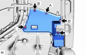
| (a) for LH Side: (1) Remove the bolt and clip (A). (2) Disengage the 2 grommets (B) and clip (C) to remove the No. 2 floor under cover. |
|
5. REMOVE NO. 1 FLOOR UNDER COVER (for HV Model)
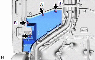
| (a) for RH Side: (1) Remove the bolt and clip (A). (2) Disengage the 2 grommets (B) to remove the No. 1 floor under cover. |
|
6. SEPARATE NO. 2 PARKING BRAKE WIRE ASSEMBLY (w/o AVS)
| (a) Disengage the 2 clamps. |
|
(b) Remove the nut and separate the No. 2 parking brake wire assembly from the rear trailing arm assembly.
7. SEPARATE NO. 2 PARKING BRAKE WIRE ASSEMBLY (w/ AVS)
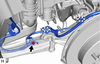
| (a) Disconnect the connector. |
|
.png)
| (b) Remove the nut and disengage the clamp. |
|
.png)
| (c) Disengage the clamp and separate the No. 2 parking brake wire assembly from the rear flexible hose bracket. |
|
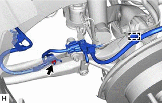
(d) Remove the nut and separate the No. 2 parking brake wire assembly from the rear trailing arm assembly.
8. REMOVE REAR STABILIZER LINK ASSEMBLY
Click here
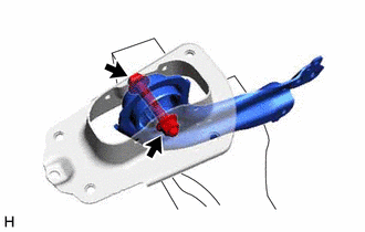
9. REMOVE REAR TRAILING ARM ASSEMBLY
| (a) Using a transmission jack and a wooden block, support the rear No. 2 suspension arm assembly. NOTICE:
|
|

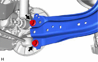
| (b) Remove the 2 bolts and separate the rear trailing arm assembly from the rear axle carrier sub-assembly. |
|
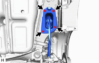
| (c) Remove the 4 bolts and rear trailing arm assembly. |
|
10. REMOVE REAR SUSPENSION ARM COVER
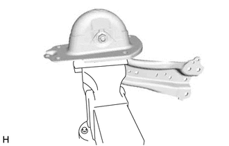
| (a) Secure the rear trailing arm assembly in a vise using aluminum plates. NOTICE: Do not overtighten the vise. |
|
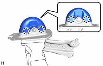
| (b) Disengage the 4 claws and remove the rear suspension arm cover. |
|
11. REMOVE REAR SUSPENSION ARM BRACKET
| (a) Remove the bolt, nut and rear suspension arm bracket from the rear trailing arm assembly. |
|
READ NEXT:
 Removal
REMOVAL CAUTION / NOTICE / HINT The necessary procedures (adjustment, calibration, initialization, or registration) that must be performed after parts are removed and installed, or replaced during rea
Installation
INSTALLATION CAUTION / NOTICE / HINT HINT:
Use the same procedure for the RH side and LH side.
The following procedure is for the LH side.
PROCEDURE 1. INSTALL REAR SUSPENSION ARM BRACKET (
Installation
INSTALLATION CAUTION / NOTICE / HINT HINT:
Use the same procedure for the RH side and LH side.
The following procedure is for the LH side.
PROCEDURE 1. INSTALL REAR SUSPENSION ARM BRACKET (
SEE MORE:
Generator Position Sensor Internal Electronic Failure (P1CAC49,P1C641F,P1CAF38)
DESCRIPTION The motor generator control ECU (MG ECU), which is built into the inverter with converter assembly, monitors its internal operation and detects malfunctions. DTC No. Detection Item DTC Detection Condition Trouble Area MIL Warning Indicate P1C641F Generator Control Modu
Brake Switch "B" Circuit Short to Battery (P070312)
DESCRIPTION The stop light switch assembly is part of a duplex system that transmits two signals: STP and ST1-. These two signals are used by the ECM to monitor whether or not the brake system is working properly. This DTC indicates that the stop light switch assembly is remaining on. When the stop
