Lexus ES: Removal
REMOVAL
CAUTION / NOTICE / HINT
The necessary procedures (adjustment, calibration, initialization, or registration) that must be performed after parts are removed and installed, or replaced during rear trailing arm assembly removal/installation are shown below.
Necessary Procedures After Parts Removed/Installed/Replaced (for HV Model:)| Replaced Part or Performed Procedure | Necessary Procedure | Effect/Inoperative Function when Necessary Procedure not Performed | Link |
|---|---|---|---|
| *1: for LED type turn signal light | |||
| Suspension, tires, etc. (The vehicle height changes because of suspension or tire replacement.) |
|
| |
| Rear television camera assembly optical axis adjustment (Back camera position setting) | Parking Assist Monitor System | | |
| Panoramic View Monitor System | | |
| Perform headlight ECU sub-assembly LH initialization*1 | Lighting System | | |
| Rear wheel alignment adjustment |
|
| |
| Replaced Part or Performed Procedure | Necessary Procedure | Effect/Inoperative Function when Necessary Procedure not Performed | Link |
|---|---|---|---|
| *1: for LED type turn signal light | |||
| Suspension, tires, etc. (The vehicle height changes because of suspension or tire replacement.) |
|
| |
| Rear television camera assembly optical axis adjustment (Back camera position setting) | Parking Assist Monitor System | | |
| Panoramic View Monitor System | | |
| Perform headlight ECU sub-assembly LH initialization*1 | Lighting System | | |
| Rear wheel alignment adjustment |
|
| |
CAUTION / NOTICE / HINT
HINT:
- Use the same procedure for the RH side and LH side.
- The following procedure is for the LH side.
PROCEDURE
1. REMOVE REAR WHEEL
Click here .gif)
2. REMOVE NO. 2 FLOOR UNDER COVER (for Gasoline Model 2WD)
(a) for LH Side:
Click here
3. REMOVE NO. 1 FLOOR UNDER COVER (for Gasoline Model 2WD)
(a) for RH Side:
Click here
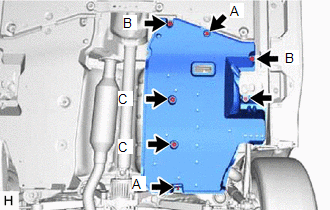
4. REMOVE NO. 2 FLOOR UNDER COVER (for HV Model)
| (a) for LH Side: (1) Remove the bolt and clip (A). (2) Disengage the 2 grommets (B) and clip (C) to remove the No. 2 floor under cover. |
|
.png)
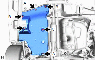
5. REMOVE NO. 1 FLOOR UNDER COVER (for HV Model)
| (a) for RH Side: (1) Remove the bolt and clip (A). (2) Disengage the 2 grommets (B) to remove the No. 1 floor under cover. |
|
.png)
6. REMOVE NO. 2 FLOOR UNDER COVER (for Gasoline Model AWD)
(a) for LH Side:
| (1) Remove the bolt and 2 clips (A). |
|
(2) Disengage the 2 grommets (B) and 2 clips (C) to remove the No. 2 floor under cover.
7. REMOVE NO. 1 FLOOR UNDER COVER (for Gasoline Model AWD)
(a) for RH Side:
| (1) Remove the bolt and 2 clips (A). |
|
(2) Disengage the 2 grommets (B) and clip (C) to remove the No. 1 floor under cover.
8. SEPARATE NO. 2 PARKING BRAKE WIRE ASSEMBLY (w/o AVS)
| (a) Disengage the 2 clamps. |
|
.png)
(b) Remove the nut and separate the No. 2 parking brake wire assembly from the rear trailing arm assembly.
9. SEPARATE NO. 2 PARKING BRAKE WIRE ASSEMBLY (w/ AVS)
| (a) Disconnect the connector. |
|
.png)
| (b) Remove the nut and disengage the clamp. |
|
.png)
| (c) Disengage the clamp and separate the No. 2 parking brake wire assembly from the rear flexible hose bracket. |
|
.png)
(d) Remove the nut and separate the No. 2 parking brake wire assembly from the rear trailing arm assembly.
10. REMOVE REAR STABILIZER LINK ASSEMBLY (for 2WD)
Click here
11. REMOVE REAR TRAILING ARM ASSEMBLY
| (a) Using a transmission jack and a wooden block, support the rear No. 2 suspension arm assembly. NOTICE:
|
|
.png)
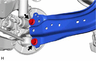
(b) for 2WD:
| (1) Remove the 2 bolts and separate the rear trailing arm assembly from the rear axle carrier sub-assembly. |
|
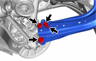
(c) for AWD:
| (1) Remove the 3 bolts, nut and separate the rear trailing arm assembly from the rear axle carrier sub-assembly. |
|
| (d) Remove the 4 bolts and rear trailing arm assembly. |
|
.png)
12. REMOVE REAR SUSPENSION ARM COVER
| (a) Secure the rear trailing arm assembly in a vise using aluminum plates. NOTICE: Do not overtighten the vise. |
|
.png)
| (b) Disengage the 4 claws and remove the rear suspension arm cover. |
|
.png)
13. REMOVE REAR SUSPENSION ARM BRACKET
| (a) Remove the bolt, nut and rear suspension arm bracket from the rear trailing arm assembly. |
|
.png)
READ NEXT:
 Installation
INSTALLATION CAUTION / NOTICE / HINT HINT:
Use the same procedure for the RH side and LH side.
The following procedure is for the LH side.
PROCEDURE 1. INSTALL REAR SUSPENSION ARM BRACKET (
Installation
INSTALLATION CAUTION / NOTICE / HINT HINT:
Use the same procedure for the RH side and LH side.
The following procedure is for the LH side.
PROCEDURE 1. INSTALL REAR SUSPENSION ARM BRACKET (
SEE MORE:
How To Proceed With Troubleshooting
CAUTION / NOTICE / HINT HINT:
Use the following procedure to troubleshoot the panoramic view monitor system.
*: Use the Techstream.
PROCEDURE 1. VEHICLE BROUGHT TO WORKSHOP
NEXT 2. CUSTOMER PROBLEM ANALYSIS (a) Ask the customer about the problems and the co
Software Incompatibility with Body Control Module Not Programmed (U032251)
DESCRIPTION The forward recognition camera receives vehicle information from the main body ECU (multiplex network body ECU) via CAN communication. DTC U032251 is stored when the forward recognition camera cannot confirm the vehicle information from the main body ECU (multiplex network body ECU).
