Lexus ES: Installation
INSTALLATION
CAUTION / NOTICE / HINT
HINT:
- Use the same procedure for the RH side and LH side.
- The following procedure is for the LH side.
PROCEDURE
1. INSTALL REAR SUSPENSION ARM BRACKET
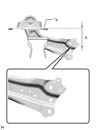
| (a) Temporarily install the rear suspension arm bracket to the rear trailing arm assembly with the bolt and nut. NOTICE: Insert the bolt from the inside of the vehicle. |
|
.png)
| (b) Position the rear trailing arm assembly as shown in the illustration. Reference Length (A): 120 mm (4.72 in.) |
|
(c) Fully tighten the nut.
Torque:
120 N·m {1224 kgf·cm, 89 ft·lbf}
2. INSTALL REAR SUSPENSION ARM COVER
(a) Engage the 4 claws and install the rear suspension arm cover.
3. INSTALL REAR TRAILING ARM ASSEMBLY
(a) Using a transmission jack and a wooden block, support the rear No. 2 suspension arm assembly.
NOTICE:
- When jacking up the rear No. 2 suspension arm assembly, be sure to jack it up slowly.
- Make sure to perform this operation with the vehicle kept as low as possible.
(b) Install the rear trailing arm assembly to the vehicle with the 4 bolts.
Torque:
90 N·m {918 kgf·cm, 66 ft·lbf}
(c) Install the rear trailing arm assembly to the rear axle carrier sub-assembly with the 2 bolts.
Torque:
135 N·m {1377 kgf·cm, 100 ft·lbf}
4. INSTALL NO. 2 PARKING BRAKE WIRE ASSEMBLY (w/o AVS)
| (a) Install the No. 2 parking brake wire assembly to the rear trailing arm assembly with the nut. Torque: 15.5 N·m {158 kgf·cm, 11 ft·lbf} |
|
.png)
(b) Engage the 2 clamps.
5. INSTALL NO. 2 PARKING BRAKE WIRE ASSEMBLY (w/ AVS)
| (a) Install the No. 2 parking brake wire assembly to the rear trailing arm assembly with the nut. Torque: 15.5 N·m {158 kgf·cm, 11 ft·lbf} |
|
.png)
(b) Engage the clamp.
| (c) Engage the guide and install the wire harness bracket. |
|
.png)
(d) Install the nut.
Torque:
8.5 N·m {87 kgf·cm, 75 in·lbf}
(e) Engage the clamp and install the No. 2 parking brake wire assembly to the wire harness bracket.
| (f) Connect the connector. |
|
.png)
6. INSTALL REAR STABILIZER LINK ASSEMBLY
Click here .gif)
7. INSTALL NO. 1 FLOOR UNDER COVER (for HV Model)
| (a) for RH Side: (1) Install the No. 1 floor under cover with the 2 grommets (B). (2) Install the bolt and clip (A). Torque: Bolt : 7.5 N·m {76 kgf·cm, 66 in·lbf} |
|
.png)
8. INSTALL NO. 2 FLOOR UNDER COVER (for HV Model)
| (a) for LH Side: (1) Install the No. 2 floor under cover with the 2 grommets (B) and clip (C). (2) Install the bolt and clip (A). Torque: Bolt : 7.5 N·m {76 kgf·cm, 66 in·lbf} |
|
.png)
9. INSTALL NO. 1 FLOOR UNDER COVER (for Gasoline Model)
(a) for RH Side:
Click here
10. INSTALL NO. 2 FLOOR UNDER COVER (for Gasoline Model)
(a) for LH Side:
Click here
11. INSTALL REAR WHEEL
Click here
12. INSPECT AND ADJUST REAR WHEEL ALIGNMENT
Click here
13. PERFORM INITIALIZATION
for HV Model:| *1: for LED type turn signal light | |
| |
| Parking Assist Monitor System | |
| Panoramic View Monitor System | |
| Lighting System*1 | |
| *1: for LED type turn signal light | |
| |
| Parking Assist Monitor System | |
| Panoramic View Monitor System | |
| Lighting System*1 | |
READ NEXT:
 Installation
INSTALLATION CAUTION / NOTICE / HINT HINT:
Use the same procedure for the RH side and LH side.
The following procedure is for the LH side.
PROCEDURE 1. INSTALL REAR SUSPENSION ARM BRACKET (
Components
COMPONENTS ILLUSTRATION *1 REAR SUSPENSION MEMBER SUB-ASSEMBLY *2 REAR UPPER CONTROL ARM ASSEMBLY LH *3 REAR UPPER CONTROL ARM ASSEMBLY RH - - Tightening torque for "Major a
SEE MORE:
Lost Communication with Panoramic View Monitor Control Module (U023B)
DESCRIPTION These DTCs are stored if there is a malfunction in the CAN communication system connected to the rear television camera assembly. HINT: If CAN communication system DTCs are stored, they may also be stored in other systems. DTC No. Detection Item DTC Detection Condition Trouble A
Black Screen
DESCRIPTION The video signal from the rear television camera assembly is transmitted to the multi-display assembly. WIRING DIAGRAM CAUTION / NOTICE / HINT NOTICE:
If the cable was disconnected from and reconnected to the negative (-) auxiliary battery terminal, the estimated course lines may not
