Lexus ES: Removal
REMOVAL
CAUTION / NOTICE / HINT
The necessary procedures (adjustment, calibration, initialization, or registration) that must be performed after parts are removed and installed, or replaced during front stabilizer bar removal/installation are shown below.
Necessary Procedure After Parts Removed/Installed/Replaced (for HV Model:)| Replaced Part or Performed Procedure | Necessary Procedure | Effect/Inoperative Function when Necessary Procedure not Performed | Link |
|---|---|---|---|
|
*1: When performing learning using the Techstream.
Click here *2: for LED type turn signal light | |||
| Auxiliary battery terminal is disconnected/reconnected | Perform steering sensor zero point calibration | Lane control system | |
| Pre-collision system | |||
| Parking support brake system*1 | |||
| Lighting System | |||
| Memorize steering angle neutral point | Parking assist monitor system | | |
| Panoramic view monitor system | | ||
| Initialize power trunk lid system | Power trunk lid system | | |
| Replacement of ECM | Perform Vehicle Identification Number (VIN) registration | MIL illuminates | |
| Inspection After Repair |
| |
| Replacement of inverter with converter assembly | Resolver learning |
| |
| Replacement of hybrid vehicle transaxle assembly |
| ||
|
|
| |
| Suspension, tires, etc. (The vehicle height changes because of suspension or tire replacement) | Rear television camera assembly optical axis (Back camera position setting) | Parking assist monitor system | for Initialization: for Calibration: |
| Replacement of front bumper assembly | Front television camera view adjustment | Panoramic view monitor system | for Initialization: for Calibration: |
| Suspension, tires, etc. (The vehicle height changes because of suspension or tire replacement) |
| ||
| Replacement of headlight ECU sub-assembly LH |
| Lighting system | |
| Suspension, tires, etc. (The vehicle height changes because of suspension or tire replacement) | Perform headlight ECU sub-assembly LH initialization*2 | ||
| Front wheel alignment adjustment |
|
| |
| Rack and pinion power steering gear assembly |
|
| |
NOTICE:
- After the power switch is turned off, the radio receiver assembly records various types of memory and settings. As a result, after turning the power switch off, make sure to wait at least 85 seconds before disconnecting the cable from the negative (-) auxiliary battery terminal. (for Audio and Visual System)
- After the power switch is turned off, the radio receiver assembly records various types of memory and settings. As a result, after turning the power switch off, make sure to wait at least 85 seconds before disconnecting the cable from the negative (-) auxiliary battery terminal. (for Navigation System)
CAUTION / NOTICE / HINT
Necessary Procedure After Parts Removed/Installed/Replaced (for Gasoline Model:)| Replaced Part or Performed Procedure | Necessary Procedure | Effect/Inoperative Function when Necessary Procedure not Performed | Link |
|---|---|---|---|
|
*1: When performing learning using the Techstream.
Click here *2: When the ECM is replaced with a new one, reset memory is unnecessary. | |||
| Battery terminal is disconnected/reconnected | Perform steering sensor zero point calibration | Lane Control System | |
| Pre-collision System | |||
| Parking Support Brake System*1 | |||
| Lighting System | |||
| Memorize steering angle neutral point | Parking Assist Monitor System | | |
| Panoramic View Monitor System | | ||
| Initialize power trunk lid system | Power Trunk Lid System | | |
| Replacement of ECM | Vehicle Identification Number (VIN) registration | MIL comes on | |
| ECU communication ID registration (Immobiliser system) | Engine start function | | |
| Inspection after repair |
| |
| Replacement of automatic transaxle assembly |
|
| for Initialization: for Registration: |
| Replacement of ECM (If transaxle compensation code read from ECM) |
| ||
| Replacement of ECM (If transaxle compensation code not read from ECM) |
| ||
| Replacement of ECM | Code registration (Smart access system with push-button start (for Start Function, Gasoline Model) |
| |
| Replacement of automatic transaxle fluid | ATF thermal degradation estimate reset | The value of the Data List item "ATF Thermal Degradation Estimate" is not estimated correctly | |
| Suspension, tires, etc. (The vehicle height changes because of suspension or tire replacement) | Rear television camera assembly optical axis adjustment (Back camera position setting) | Parking Assist Monitor System | for Initialization: for Calibration: |
| Perform headlight ECU sub-assembly LH initialization | Lighting system | | |
| Replacement of front bumper assembly | Front television camera view adjustment | Panoramic View Monitor System | for Initialization: for Calibration: |
| Suspension, tires, etc. (The vehicle height changes because of suspension or tire replacement) |
| ||
| Front wheel alignment adjustment |
|
| |
| Rack and pinion power steering gear assembly |
|
| |
NOTICE:
- After the engine switch is turned off, the radio receiver assembly records various types of memory and settings. As a result, after turning the engine switch off, make sure to wait at least 85 seconds before disconnecting the cable from the negative (-) battery terminal. (for Audio and Visual System)
- After the engine switch is turned off, the radio receiver assembly records various types of memory and settings. As a result, after turning the engine switch off, make sure to wait at least 85 seconds before disconnecting the cable from the negative (-) battery terminal. (for Navigation System)
PROCEDURE
1. REMOVE ENGINE ASSEMBLY WITH TRANSAXLE
for A25A-FXS: Click here .gif)
for 2GR-FKS: Click here
2. REMOVE FRONT STABILIZER LINK ASSEMBLY LH
| (a) Remove the cap from the nut. |
|
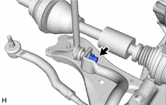
| (b) Remove the nut and front stabilizer link assembly LH from the front stabilizer bar. NOTICE: Do not damage the boot of the ball joint. HINT: If the ball joint turns together with the nut, use a 6 mm hexagon socket wrench to hold the stud bolt. |
|
3. REMOVE FRONT STABILIZER LINK ASSEMBLY RH
HINT:
Perform the same procedure as for the LH side.
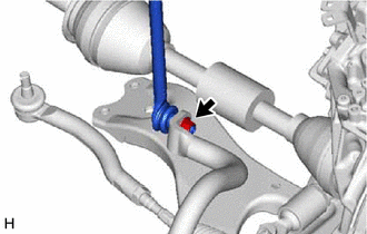
4. REMOVE FRONT NO. 1 STABILIZER BRACKET LH
| (a) Remove the 2 bolts and front No. 1 stabilizer bracket LH from the front frame assembly. |
|
5. REMOVE FRONT NO. 1 STABILIZER BRACKET RH
HINT:
Perform the same procedure as for the LH side.
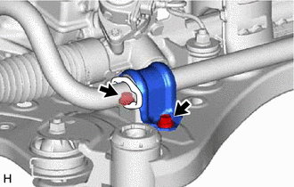
6. REMOVE FRONT STABILIZER BAR
(a) Remove the front stabilizer bar with 2 front stabilizer bar bushings from the front frame assembly.
7. REMOVE FRONT NO. 1 STABILIZER BAR BUSHING (for LH Side)
(a) Remove the front No. 1 stabilizer bar bushing from the front stabilizer bar.
8. REMOVE FRONT NO. 1 STABILIZER BAR BUSHING (for RH Side)
HINT:
Perform the same procedure as for the LH side.
READ NEXT:
 Inspection
INSPECTION PROCEDURE 1. INSPECT FRONT STABILIZER LINK ASSEMBLY (a) Inspect the turning torque of the ball joint. (1) Secure the front stabilizer link assembly in a vise using aluminum plates. NOTIC
Installation
INSTALLATION PROCEDURE 1. INSTALL FRONT NO. 1 STABILIZER BAR BUSHING (for LH Side) (a) Install the front No. 1 stabilizer bar bushing to the front stabilizer bar as shown in the illustration. *a
Installation
INSTALLATION PROCEDURE 1. INSTALL FRONT NO. 1 STABILIZER BAR BUSHING (for LH Side) (a) Install the front No. 1 stabilizer bar bushing to the front stabilizer bar as shown in the illustration. *a
SEE MORE:
PBD/PTL Closer Operation (B2250)
DESCRIPTION DTC B2250 is stored when there is a malfunction in the closer pulse sensor circuit of the luggage door closer assembly and when a normal waveform is not input for the closer pulse during power trunk lid operation. DTC No. Detection Item DTC Detection Condition Trouble Area B
Data List / Active Test
DATA LIST / ACTIVE TEST DATA LIST HINT: Using the Techstream to read the Data List allows the values or states of switches, sensors, actuators and other items to be read without removing any parts. This non-intrusive inspection can be very useful because intermittent conditions or signals may be dis
