Lexus ES: Installation
INSTALLATION
PROCEDURE
1. INSTALL FRONT NO. 1 STABILIZER BAR BUSHING (for LH Side)
(a) Install the front No. 1 stabilizer bar bushing to the front stabilizer bar as shown in the illustration.
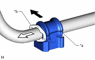
| *a | Cutout |
| *b | Stopper Ring |
.png) | Front of the Vehicle |
.png) | Outside of the Vehicle |
NOTICE:
- Install the front No. 1 stabilizer bar bushing so that the cutout is facing the rear of the vehicle.
- Install the front No. 1 stabilizer bar bushing onto the front stabilizer bar so that the stopper ring of the front stabilizer bar faces the outside of the vehicle.
2. INSTALL FRONT NO. 1 STABILIZER BAR BUSHING (for RH Side)
HINT:
Perform the same procedure as for the LH side.
3. INSTALL FRONT STABILIZER BAR
(a) Install the front stabilizer bar with the 2 front stabilizer bar bushings to the front frame assembly.
NOTICE:
Make sure that the identification mark is positioned as shown in the illustration.
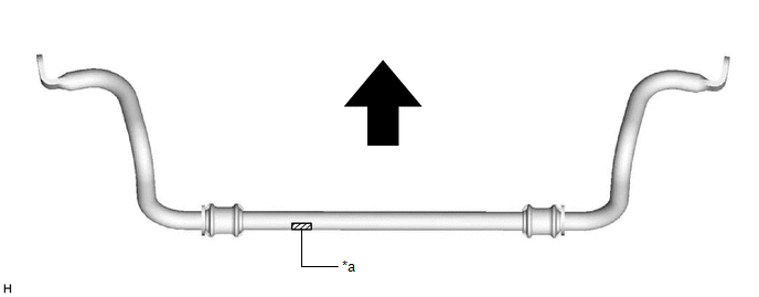
| *a | Identification Mark | - | - |
| | Front of the Vehicle | - | - |
4. INSTALL FRONT NO. 1 STABILIZER BRACKET LH
(a) Install the front No. 1 stabilizer bracket LH to the front frame assembly with the 2 bolts.
Torque:
44 N·m {449 kgf·cm, 32 ft·lbf}
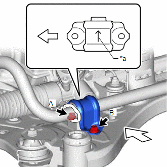
| *a | Arrow |
| | Front of the Vehicle |
NOTICE:
- Make sure to install the front No. 1 stabilizer bracket LH with its arrow facing the inside of the vehicle.
- Temporarily tighten the bolt (A) and (B), and then fully tighten the 2 bolts in the order of (A) and (B).
5. INSTALL FRONT NO. 1 STABILIZER BRACKET RH
HINT:
Perform the same procedure as for the LH side.
6. INSTALL FRONT STABILIZER LINK ASSEMBLY LH
(a) Install the front stabilizer link assembly LH to the front stabilizer bar with the nut.
Torque:
74 N·m {755 kgf·cm, 55 ft·lbf}
NOTICE:
Do not damage the boot of the ball joint.
HINT:
If the ball joint turns together with the nut, use a 6 mm hexagon socket wrench to hold the stud bolt.
(b) Install the cap to the nut.
7. INSTALL FRONT STABILIZER LINK ASSEMBLY RH
HINT:
Perform the same procedure as for the LH side.
8. INSTALL ENGINE ASSEMBLY WITH TRANSAXLE
for A25A-FXS: Click here .gif)
for 2GR-FKS: Click here
READ NEXT:
 Installation
INSTALLATION PROCEDURE 1. INSTALL FRONT NO. 1 STABILIZER BAR BUSHING (for LH Side) (a) Install the front No. 1 stabilizer bar bushing to the front stabilizer bar as shown in the illustration. *a
Components
COMPONENTS ILLUSTRATION *A for A25A-FXS - - *1 FRONT FRAME ASSEMBLY *2 FUEL DELIVERY GUARD *3 STEERING GEAR HEAT INSULATOR *4 WIRE HARNESS *5 FRONT ENGINE MOUNTING
SEE MORE:
Components
COMPONENTS ILLUSTRATION *1 BATTERY CLAMP SUB-ASSEMBLY - - N*m (kgf*cm, ft.*lbf): Specified torque - - ILLUSTRATION *1 FRONT LOWER NO. 1 FLOOR HEAT INSULATOR - - N*m (kgf*cm, ft.*lbf): Specified torque - - ILLUSTRATION *1 NO. 1 CONSOLE BOX DUCT
Tire Pressure Warning Light Circuit
DESCRIPTION If the tire pressure warning ECU and receiver detects any problems, the tire pressure warning light blinks for 1 minute then illuminates, and tire pressure monitoring is disabled at the same time. At this time, the ECU stores a DTC in memory. The tire pressure warning ECU and receiver se
