Lexus ES: Removal
REMOVAL
CAUTION / NOTICE / HINT
The necessary procedures (adjustment, calibration, initialization, or registration) that must be performed after parts are removed and installed, or replaced during front lower ball joint assembly removal/installation are shown below.
Necessary Procedures After Parts Removed/Installed/Replaced (for HV Model:)| Replaced Part or Performed Procedure | Necessary Procedure | Effect/Inoperative Function when Necessary Procedure not Performed | Link |
|---|---|---|---|
|
*: When performing learning using the Techstream.
Click here | |||
| Auxiliary battery terminal is disconnected/reconnected | Perform steering sensor zero point calibration | Lane Control System | |
| Pre-collision System | |||
| Parking Support Brake System* | |||
| Lighting System | |||
| Memorize steering angle neutral point | Parking Assist Monitor System | | |
| Panoramic View Monitor System | | ||
| Initialize power trunk lid system | Power Trunk Lid System (for HV Model) | | |
| Front wheel alignment adjustment |
|
| |
NOTICE:
for HV Model:- After the power switch is turned off, the radio receiver assembly records various types of memory and settings. As a result, after turning the power switch off, make sure to wait at least 85 seconds before disconnecting the cable from the negative (-) auxiliary battery terminal. (for Audio and Visual System)
- After the power switch is turned off, the radio receiver assembly records various types of memory and settings. As a result, after turning the power switch off, make sure to wait at least 85 seconds before disconnecting the cable from the negative (-) auxiliary battery terminal. (for Navigation System)
CAUTION / NOTICE / HINT
Necessary Procedures After Parts Removed/Installed/Replaced (for Gasoline Model:)| Replaced Part or Performed Procedure | Necessary Procedure | Effect/Inoperative Function when Necessary Procedure not Performed | Link |
|---|---|---|---|
| Front wheel alignment adjustment |
|
| |
- When removing or installing the rear disc brake caliper assembly, pushing back the disc brake piston may cause a large clearance between the brake pads and brake disc. When the brake pedal is depressed with a large clearance between the brake pads and the brake disc, DTC C1214 related to abnormal brake fluid pressure may be stored. Make sure to clear any DTCs after performing this procedure.
- While the auxiliary battery is connected, even if the power switch is off, the brake control system activates when the brake pedal is depressed or any door courtesy switch turns on. Therefore, when servicing the brake system components, do not operate the brake pedal or open/close the doors while the auxiliary battery is connected.
HINT:
- Use the same procedure for the RH side and LH side.
- The following procedure is for the LH side.
PROCEDURE
1. REMOVE FRONT AXLE ASSEMBLY
Click here .gif)
2. REMOVE FRONT LOWER BALL JOINT ASSEMBLY
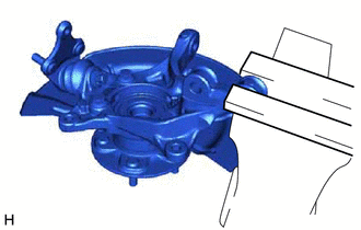
| (a) Secure the front axle assembly in a vise using aluminum plates. NOTICE: Do not overtighten the vise. |
|
| (b) Remove the cotter pin. |
|
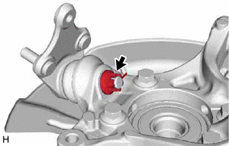
(c) Remove the nut.
| (d) Install SST to the front lower ball joint assembly as shown in the illustration. SST: 09960-20010 09961-02050 NOTICE: Check that the clearance measurement between SST and the front axle assembly is 1 mm (0.0394 in.). |
|
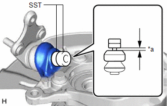
(e) Using SST, remove the front lower ball joint assembly from the front axle assembly as shown in the illustration.
SST: 09960-20010
09961-02010
09961-02050

| *a | Center Nut |
| *b | Molybdenum Grease Application Area |
| *c | Place wrench here |
| *d | String |
 | Turn |
CAUTION:
Apply molybdenum grease to the threads and end of the SST bolt.
NOTICE:
- Be sure to tighten the string firmly to secure SST to the front axle assembly to prevent SST from falling off.
- Install SST with the center nut so that (A) and (B) shown in the illustration are parallel. Otherwise, the front lower ball joint dust cover may be damaged.
- Be sure to place a wrench on the part shown in the illustration.
- Do not damage the front lower ball joint dust cover.
- Do not damage the steering knuckle.
- Do not damage the front disc brake dust cover.
READ NEXT:
 Inspection
INSPECTION PROCEDURE 1. INSPECT FRONT LOWER BALL JOINT ASSEMBLY (a) Inspect the turning torque of the ball joint. (1) Secure the front lower ball joint assembly in a vise using aluminum plates. (2)
Installation
INSTALLATION CAUTION / NOTICE / HINT for HV Model:
When removing or installing the front disc brake caliper assembly, pushing back the disc brake piston may cause a large clearance between the brak
SEE MORE:
Rear Power Window RH does not Operate with Rear Power Window Switch RH
DESCRIPTION When the power switch is on (IG), the power window regulator motor assembly (for rear RH door) is operated by the rear power window regulator switch assembly (for RH door). The power window regulator motor assembly (for rear RH door) has motor, regulator, and ECU functions. WIRING DIAGRA
Removal
REMOVAL PROCEDURE 1. REMOVE FRONT DOOR SCUFF PLATE LH Click here 2. REMOVE COWL SIDE TRIM BOARD LH Click here 3. REMOVE FRONT DOOR OPENING TRIM COVER LH Click here 4. REMOVE INSTRUMENT SIDE PANEL LH Click here 5. REMOVE NO. 1 INSTRUMENT PANEL UNDER COVER SUB-ASSEMBLY Click here 6. REMOVE L
