Lexus ES: Removal
REMOVAL
PROCEDURE
1. REMOVE FORWARD RECOGNITION CAMERA
Click here .gif)
2. REMOVE FORWARD RECOGNITION WITH HEATER HOOD SUB-ASSEMBLY
NOTICE:
- Do not touch the inner surface of the forward recognition with heater hood sub-assembly.
- Do not apply force to the heating element of the forward recognition with heater hood sub-assembly or an open circuit may result.
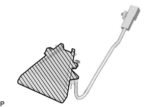
.png) | Inner Surface of Forward Recognition with Heater Hood Sub-assembly |
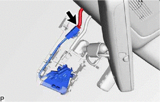
| (a) Disconnect the connector. NOTICE: Do not pull the harness forcibly when disconnecting the connector. |
|
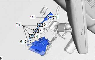
| (b) Disengage the clamp and 4 ribs. HINT: Disengage the clamp and ribs in the order shown in the illustration. |
|
(c) Pull the forward recognition with heater hood sub-assembly in the direction indicated by the arrow (1) shown in the illustration to disengage the 2 claws.
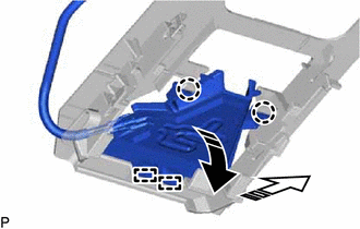
.png) | Remove in this Direction (1) |
.png) | Remove in this Direction (2) |
(d) Pull the forward recognition with heater hood sub-assembly in the direction indicated by the arrow (2) shown in the illustration to disengage the 2 guides and remove the forward recognition with heater hood sub-assembly.
READ NEXT:
 Installation
INSTALLATION PROCEDURE 1. INSTALL FORWARD RECOGNITION WITH HEATER HOOD SUB-ASSEMBLY NOTICE:
Do not touch the inner surface of the forward recognition with heater hood sub-assembly. Inner Sur
Precaution
PRECAUTION PRECAUTION FOR DISCONNECTING CABLE FROM NEGATIVE BATTERY TERMINAL NOTICE: When disconnecting the cable from the negative (-) battery terminal, initialize the following system(s) after the c
SEE MORE:
Installation
INSTALLATION PROCEDURE 1. INSTALL REAR DIFFERENTIAL SUPPORT (a) Install the rear differential support to the rear differential carrier assembly with 4 new bolts. Torque: 72 N·m {734 kgf·cm, 53 ft·lbf} 2. INSTALL REAR NO. 1 DIFFERENTIAL SUPPORT (a) Install the rear No. 1 differential support to t
Precaution
PRECAUTION PRECAUTION FOR DISCONNECTING CABLE FROM NEGATIVE BATTERY TERMINAL NOTICE: When disconnecting the cable from the negative (-) battery terminal, initialize the following systems after the cable is reconnected. System Name See Procedure Lane Control System (for Gasoline Model)
