Lexus ES: Installation
Lexus ES (XZ10) Service Manual / Engine & Hybrid System / Cruise Control / Camera Heater / Installation
INSTALLATION
PROCEDURE
1. INSTALL FORWARD RECOGNITION WITH HEATER HOOD SUB-ASSEMBLY
NOTICE:
-
Do not touch the inner surface of the forward recognition with heater hood sub-assembly.
.png)
.png)
Inner Surface of Forward Recognition with Heater Hood Sub-assembly
- Do not apply force to the heating element of the forward recognition with heater hood sub-assembly or an open circuit may result.
(a) Engage the 2 guides and 2 claws as indicated by the arrows in the order shown in the illustration.
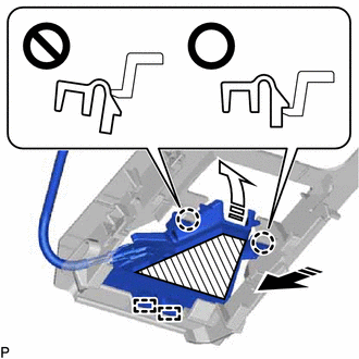
| | Heater Area |
.png) | Install in this Direction (1) |
.png) | Install in this Direction (2) |
NOTICE:
- Make sure that the 2 claws are engaged as shown in the illustration. Failure to do so may result in the malfunction of systems that use the forward recognition camera.
- Do not apply force to the heating element of the forward recognition with heater hood sub-assembly or an open circuit may result.
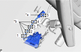
| (b) Engage the clamp and 4 ribs to install the forward recognition with heater hood sub-assembly. NOTICE:
HINT: Engage the clamp and ribs in the order shown in the illustration. |
|
(c) Connect the connector.
2. INSTALL FORWARD RECOGNITION CAMERA
Click here .gif)
READ NEXT:
 Precaution
PRECAUTION PRECAUTION FOR DISCONNECTING CABLE FROM NEGATIVE BATTERY TERMINAL NOTICE: When disconnecting the cable from the negative (-) battery terminal, initialize the following system(s) after the c
Definition Of Terms
DEFINITION OF TERMS Term Definition Monitor description Description of what the ECM monitors and how it detects malfunctions (monitoring purpose and details). Related DTCs Group of di
SEE MORE:
Steering Angle Initialization Incomplete (C1694)
DESCRIPTION This DTC is stored when the rear television camera assembly judges that the maximum steering angle has not been memorized (steering angle setting is incomplete). DTC No. Detection Item DTC Detection Condition Trouble Area C1694 Steering Angle Initialization Incomplete Ma
Disposal
DISPOSAL PROCEDURE 1. DISPOSE OF HOOD SUPPORT ASSEMBLY (a) Secure the hood support assembly horizontally in a vise with the piston rod pulled out. (b) Wearing safety glasses, gradually cut a part within the area (a) shown in the illustration using a metal saw to release the gas. Specification:
© 2016-2026 Copyright www.lexguide.net
