Lexus ES: Removal
REMOVAL
CAUTION / NOTICE / HINT
The necessary procedures (adjustment, calibration, initialization or registration) that must be performed after parts are removed and installed, or replaced during fuel pump assembly removal/installation are shown below.
Necessary Procedures After Parts Removed/Installed/Replaced| Replaced Part or Performed Procedure | Necessary Procedure | Effect/Inoperative Function when Necessary Procedure not Performed | Link |
|---|---|---|---|
|
*: When performing learning using the Techstream.
Click here | |||
| Auxiliary battery terminal is disconnected/reconnected | Perform steering sensor zero point calibration | Lane Control System (for HV Model) | |
| Pre-collision System (for HV Model) | |||
| Parking Support Brake System (for HV Model)* | |||
| Lighting System (for HV Model) | |||
| Memorize steering angle neutral point | Parking Assist Monitor System (for HV Model) | | |
| Panoramic View Monitor System (for HV Model) | | ||
| Initialize power trunk lid system | Power Trunk Lid System (for HV Model) | | |
| Inspection after repair |
| |
CAUTION:
-
Never perform work on fuel system components near any possible ignition sources.
.png)
- Vaporized fuel could ignite, resulting in a serious accident.
-
Do not perform work on fuel system components without first disconnecting the cable from the negative (-) auxiliary battery terminal.
.png)
- Sparks could cause vaporized fuel to ignite, resulting in a serious accident.
-
To prevent serious injury due to fuel spray from the high-pressure fuel lines, always discharge fuel system pressure before removing any fuel system components.
.png)
NOTICE:
- After the power switch is turned off, the radio receiver assembly records various types of memory and settings. As a result, after turning the power switch off, make sure to wait at least 85 seconds before disconnecting the cable from the negative (-) auxiliary battery terminal. (for Audio and Visual System)
- After the power switch is turned off, the radio receiver assembly records various types of memory and settings. As a result, after turning the power switch off, make sure to wait at least 85 seconds before disconnecting the cable from the negative (-) auxiliary battery terminal. (for Navigation System)
-
This procedure includes the removal of small-head bolts. Refer to Small-Head Bolts of Basic Repair Hint to identify the small-head bolts.
Click here
.gif)
PROCEDURE
1. PRECAUTION
NOTICE:
After turning the power switch off, waiting time may be required before disconnecting the cable from the negative (-) auxiliary battery terminal. Therefore, make sure to read the disconnecting the cable from the negative (-) auxiliary battery terminal notices before proceeding with work.
2. DISCHARGE FUEL SYSTEM PRESSURE
Click here
3. DISCONNECT CABLE FROM NEGATIVE AUXILIARY BATTERY TERMINAL
Click here
4. REMOVE THROTTLE BODY WITH MOTOR ASSEMBLY
Click here
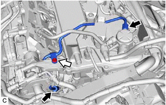
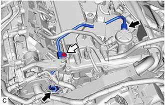
5. DISCONNECT FUEL TUBE SUB-ASSEMBLY
| (a) Remove the fuel pipe clamp from the fuel tube connector. |
|
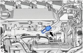
| (b) Disconnect the fuel tube sub-assembly from the fuel pump assembly and fuel delivery pipe sub-assembly. Click here |
|
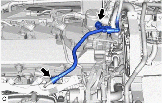
6. REMOVE NO. 2 WATER BY-PASS PIPE
| (a) Disengage the clamp to disconnect the HV air conditioning wire. |
|
| (b) Slide the clip and disconnect the No. 8 water by-pass hose from the No. 2 water by-pass pipe. |
|
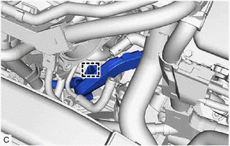
| (c) Using an 8 mm socket wrench, remove the 2 bolts (A) and separate the No. 2 water by-pass pipe from the intake manifold. |
|
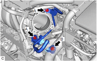
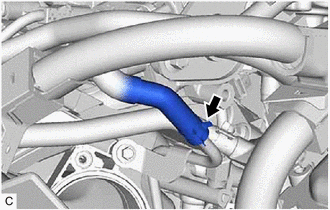
(d) Remove the bolt (B) and No. 2 water by-pass pipe from the cylinder block sub-assembly.
7. REMOVE NO. 1 FUEL PIPE SUB-ASSEMBLY
CAUTION:
To prevent serious injury due to fuel spray from the high-pressure fuel lines, always discharge fuel system pressure before removing any fuel system components.
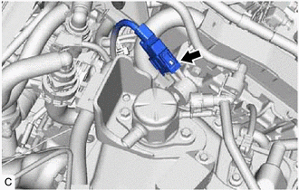
| (a) Disconnect the ignition coil connector. |
|
.png)
(b) for EGR Valve Bracket Connection Type:
(1) Using a 17 mm union nut wrench, loosen the 2 union nuts of the No. 1 fuel pipe sub-assembly.
.png) | Union Nut |
.png) | Bolt |
(2) Using an 8 mm socket wrench, remove the bolt.
(c) for Cylinder Head Cover Sub-assembly Connection Type:
(1) Using a 17 mm union nut wrench, loosen the 2 union nuts of the No. 1 fuel pipe sub-assembly.
| | Union Nut |
| | Bolt |
(2) Using an 8 mm socket wrench, remove the bolt.
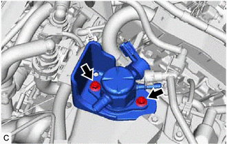
| (d) Loosen the 2 bolts of the fuel pump assembly. |
|
.png)
(e) Remove the No. 1 fuel pipe sub-assembly from the fuel delivery pipe and fuel pump assembly.
8. REMOVE FUEL PUMP ASSEMBLY
NOTICE:
When replacing the fuel pump assembly, it is necessary to replace the No. 1 fuel pipe sub-assembly with a new one.
| (a) Disconnect the fuel pump assembly connector. |
|
| (b) Remove the 2 bolts, fuel pump assembly and fuel pump flange from the cylinder head cover sub-assembly. |
|
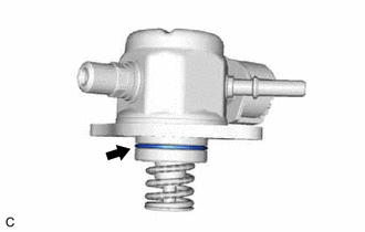
| (c) Remove the O-ring from the fuel pump assembly. |
|
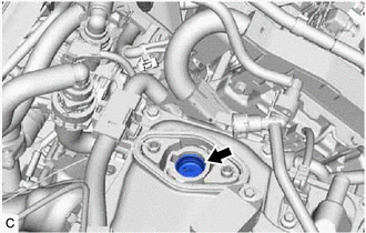
| (d) Remove the fuel pump lifter assembly from the fuel pump lifter guide. |
|
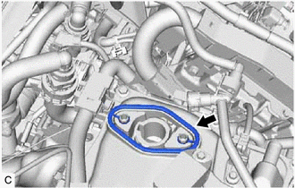
| (e) Remove the fuel pump spacer gasket from the cylinder head cover sub-assembly. |
|
READ NEXT:
 Inspection
INSPECTION PROCEDURE 1. INSPECT FUEL PUMP ASSEMBLY (a) Measure the resistance according to the value(s) in the table below. Standard Resistance: Tester Connection Condition Specified Condit
Installation
INSTALLATION CAUTION / NOTICE / HINT NOTICE: This procedure includes the installation of small-head bolts. Refer to Small-Head Bolts of Basic Repair Hint to identify the small-head bolts. Click here
SEE MORE:
CAN Communication Failure (Message Registry) (U1000)
DESCRIPTION The headlight ECU sub-assembly LH or headlight ECU sub-assembly RH stores this DTC if it detects an internal malfunction related to the CAN communication system. for LED Type Turn Signal Light DTC No. Detection Item DTC Detection Condition Trouble Area DTC Output from U100
Backup Battery Internal Electronic Failure (B15CC49)
DESCRIPTION This DTC is set when the DCM (telematics transceiver) detects one of the following:
The mobilephone battery voltage drops or the mobilephone battery malfunctions.
The mobilephone battery temperature is (temporarily) high.
DTC No. Detection Item DTC Detection Condition Tr
