Lexus ES: AVC-LAN Circuit
DESCRIPTION
Each unit of the audio and visual system connected to the AVC-LAN (communication bus) transmits signals via AVC-LAN communication.
If a short to +B or short to ground occurs in an AVC-LAN communication line, the audio and visual system will not function normally because communication is not possible.
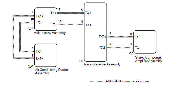
WIRING DIAGRAM
CAUTION / NOTICE / HINT
NOTICE:
-
Depending on the parts that are replaced during vehicle inspection or maintenance, performing initialization, registration or calibration may be needed. Refer to Precaution for Audio and Visual System.
Click here
.gif)
-
When replacing the radio receiver assembly, always replace it with a new one. If a radio receiver assembly which was installed to another vehicle is used, the following may occur:
- A communication malfunction DTC may be stored.
- The radio receiver assembly may not operate normally.
HINT:
The radio receiver assembly is the master unit.
PROCEDURE
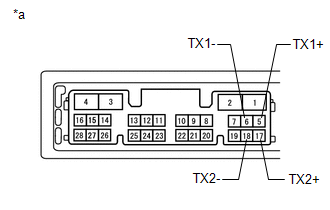
| 1. | INSPECT RADIO RECEIVER ASSEMBLY |
(a) Remove the radio receiver assembly.
Click here
| (b) Measure the resistance according to the value(s) in the table below. Standard Resistance:
|
|
| NG | .gif) | REPLACE RADIO RECEIVER ASSEMBLY |
|
.gif)
| 2. | CHECK HARNESS AND CONNECTOR (AVC-LAN CIRCUIT) |
(a) Disconnect the G6 radio receiver assembly connector.
(b) Disconnect the G9 stereo component amplifier assembly connector.
(c) Disconnect the G22 multi-display assembly connector.
(d) Disconnect the G23 air conditioning control assembly connector.
(e) Measure the resistance according to the value(s) in the table below.
Standard Resistance:
| Tester Connection | Condition | Specified Condition |
|---|---|---|
| G6-17 (TX2+) - G9-8 (TX+) | Always | Below 1 Ω |
| G6-18 (TX2-) - G9-7 (TX-) | Always | Below 1 Ω |
| G6-5 (TX1+) - G22-7 (TX+) | Always | Below 1 Ω |
| G6-6 (TX1-) - G22-19 (TX-) | Always | Below 1 Ω |
| G22-6 (TX1+) - G23-1 (TX1+) | Always | Below 1 Ω |
| G22-18 (TX1-) - G23-2 (TX1-) | Always | Below 1 Ω |
| G6-17 (TX2+) or G9-8 (TX+) - Body ground | Always | 10 kΩ or higher |
| G6-18 (TX2-) or G9-7 (TX-) - Body ground | Always | 10 kΩ or higher |
| G6-5 (TX1+) or G22-7 (TX+) - Body ground | Always | 10 kΩ or higher |
| G6-6 (TX1-) or G22-19 (TX-) - Body ground | Always | 10 kΩ or higher |
| G22-6 (TX1+) or G23-1 (TX1+) - Body ground | Always | 10 kΩ or higher |
| G22-18 (TX1-) or G23-2 (TX1-) - Body ground | Always | 10 kΩ or higher |
| NG | | REPAIR OR REPLACE HARNESS OR CONNECTOR |
|
| 3. | INSPECT MALFUNCTIONING PARTS |
(a) Disconnect and reconnect each slave unit one by one until the master unit returns to normal.
HINT:
- Check all slave units.
- If disconnecting a slave unit causes the master unit to return to normal, the slave unit is defective and should be replaced.
OK:
Master unit returns to normal.
| OK | | REPLACE MALFUNCTIONING PARTS |
| NG | | REPLACE RADIO RECEIVER ASSEMBLY |
READ NEXT:
 Stereo Component Amplifier Malfunction (B15A3)
DESCRIPTION This DTC is stored when a malfunction occurs in the stereo component amplifier assembly. DTC No. Detection Item DTC Detection Condition Trouble Area B15A3 Stereo Component A
Display Malfunction (B15A6,B15B0)
DESCRIPTION These DTCs are stored when a malfunction occurs in the multi-display assembly. DTC No. Detection Item DTC Detection Condition Trouble Area B15A6 Display Malfunction When a
GPS Antenna Connection Malfunction(short) (B15C0,B15C1)
DESCRIPTION These DTCs are stored when a malfunction occurs in the navigation antenna assembly. DTC No. Detection Item DTC Detection Condition Trouble Area B15C0 GPS Antenna Connection
SEE MORE:
Installation
INSTALLATION PROCEDURE 1. INSTALL FRONT NO. 1 STABILIZER BAR BUSHING (for LH Side) (a) Install the front No. 1 stabilizer bar bushing to the front stabilizer bar as shown in the illustration. *a Cutout *b Stopper Ring Front of the Vehicle Outside of the Vehicle NOTICE:
Removal
REMOVAL CAUTION / NOTICE / HINT The necessary procedures (adjustment, calibration, initialization or registration) that must be performed after parts are removed and installed, or replaced during front exhaust pipe assembly (TWC: Rear Catalyst), center exhaust pipe assembly and tail exhaust pipe ass
