Lexus ES: Removal
REMOVAL
CAUTION / NOTICE / HINT
The necessary procedures (adjustment, calibration, initialization or registration) that must be performed after parts are removed and installed, or replaced during engine water pump assembly (water inlet housing) removal/installation are shown below.
Necessary Procedures After Parts Removed/Installed/Replaced| Replaced Part or Performed Procedure | Necessary Procedure | Effect/Inoperative Function when Necessary Procedure not Performed | Link |
|---|---|---|---|
| Inspection After Repair |
| |
NOTICE:
This procedure includes the removal of small-head bolts. Refer to Small-Head Bolts of Basic Repair Hint to identify the small-head bolts.
Click here .gif)
PROCEDURE
1. REMOVE INTAKE MANIFOLD
Click here
2. REMOVE WATER INLET WITH THERMOSTAT SUB-ASSEMBLY
Click here
3. REMOVE ENGINE WATER PUMP ASSEMBLY (WATER INLET HOUSING)
| (a) Disconnect the sensor wire connector. |
|
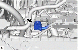
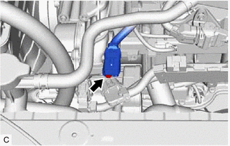
| (b) Using an 8 mm socket wrench, remove the bolt and disconnect the sensor wire from the engine water pump assembly (water inlet housing). |
|
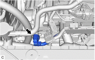
| (c) Disconnect the engine water pump assembly (water inlet housing) connector. |
|
| (d) Remove the 4 bolts and engine water pump assembly (water inlet housing) from the cylinder block assembly. |
|
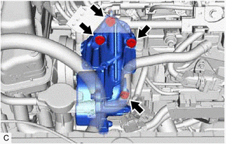
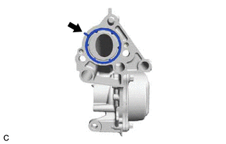
| (e) Remove the gasket from the engine water pump assembly (water inlet housing). |
|
READ NEXT:
 Installation
INSTALLATION CAUTION / NOTICE / HINT NOTICE: This procedure includes the installation of small-head bolts. Refer to Small-Head Bolts of Basic Repair Hint to identify the small-head bolts. Click here
SEE MORE:
Disassembly
DISASSEMBLY CAUTION / NOTICE / HINT The necessary procedures (adjustment, calibration, initialization, or registration) that must be performed after parts are removed and installed, or replaced during rear door removal/installation are shown below. Necessary Procedure After Parts Removed/Installed/R
Removal
REMOVAL CAUTION / NOTICE / HINT The necessary procedures (adjustment, calibration, initialization or registration) that must be performed after parts are removed and installed, or replaced during front door illumination light (front door outside handle assembly) removal/installation are shown below.
