Lexus ES: Removal
REMOVAL
CAUTION / NOTICE / HINT
The necessary procedures (adjustment, calibration, initialization or registration) that must be performed after parts are removed and installed, or replaced during flow shutting valve (water by-pass hose assembly) removal/installation are shown below.
Necessary Procedures After Parts Removed/Installed/Replaced| Replaced Part or Performed Procedure | Necessary Procedure | Effect/Inoperative Function when Necessary Procedure not Performed | Link |
|---|---|---|---|
| *: When performing learning using the Techstream. | |||
| Auxiliary battery terminal is disconnected/reconnected | Perform steering sensor zero point calibration | Lane Control System | |
| Pre-collision system | |||
| Parking Support Brake System* | |||
| Lighting system | |||
| Memorize steering angle neutral point | Parking assist monitor system | | |
| Panoramic view monitor system | | ||
| Initialize power trunk lid system | Power Trunk Lid System | | |
| Replacement of inverter with converter assembly | Resolver learning |
| |
| Replacement of ECM | Perform Vehicle Identification Number (VIN) registration | MIL illuminates | |
NOTICE:
- After the power switch is turned off, the radio receiver assembly records various types of memory and settings. As a result, after turning the power switch off, make sure to wait at least 85 seconds before disconnecting the cable from the negative (-) auxiliary battery terminal. (for Audio and Visual System)
- After the power switch is turned off, the radio receiver assembly records various types of memory and settings. As a result, after turning the power switch off, make sure to wait at least 85 seconds before disconnecting the cable from the negative (-) auxiliary battery terminal. (for Navigation System)
PROCEDURE
1. REMOVE INVERTER WITH CONVERTER ASSEMBLY
Click here .gif)
2. DRAIN ENGINE COOLANT (for Engine)
Click here
3. REMOVE FLOW SHUTTING VALVE (WATER BY-PASS HOSE ASSEMBLY)
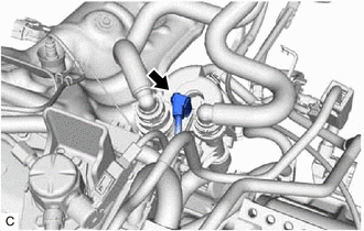
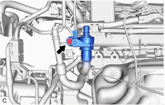
| (a) Disconnect the flow shutting valve (water by-pass hose assembly) connector. |
|
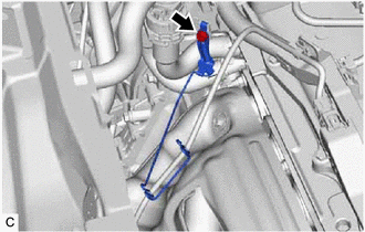
(b) Disconnect the outlet heater hose connector from the No. 2 water by-pass pipe sub-assembly.
NOTICE:
Remove any foreign matter on the No. 2 water by-pass pipe sub-assembly and outlet heater hose connector before performing this work.
(1) Pull out the retainer to disengage the lock claws and pull off the outlet heater hose connector.
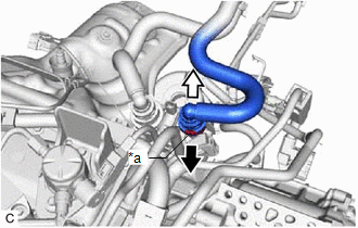
| *a | Retainer |
.png) | Pull out |
.png) | Pull off |
(2) Check that there is no foreign matter on the sealing surfaces of the disconnected water lines. Clean them if necessary.
(3) Cover the disconnected No. 2 water by-pass pipe sub-assembly and outlet heater hose connector with plastic bags to prevent damage and contamination.
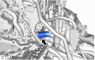
(c) Disconnect the inlet heater hose connector from the flow shutting valve (water by-pass hose assembly).
NOTICE:
Remove any foreign matter on the flow shutting valve (water by-pass hose assembly) and inlet heater hose connector before performing this work.
(1) Pull out the retainer to disengage the lock claws and pull off the inlet heater hose connector.
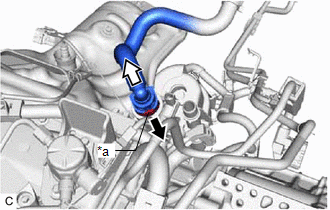
| *a | Retainer |
| | Pull out |
| | Pull off |
(2) Check that there is no foreign matter on the sealing surfaces of the disconnected water lines. Clean them if necessary.
(3) Cover the disconnected inlet heater hose connector with plastic bag to prevent damage and contamination.
| (d) Remove the bolt to disconnect the No. 2 water by-pass pipe sub-assembly. |
|
| (e) Remove the bolt to disconnect the flow shutting valve (water by-pass hose assembly). |
|
| (f) Remove the bolt and wire harness clamp bracket. |
|
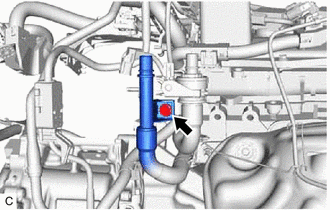
| (g) Slide the clip and disconnect the flow shutting valve (water by-pass hose assembly) from the water by-pass outlet sub-assembly. HINT: Use a container to catch any engine coolant which flows out of the flow shutting valve (water by-pass hose assembly) and water by-pass outlet sub-assembly. |
|
READ NEXT:
 Inspection
INSPECTION PROCEDURE 1. INSPECT FLOW SHUTTING VALVE (WATER BY-PASS HOSE ASSEMBLY) (a) Measure the resistance according to the value(s) in the table below. Standard Resistance: Tester Connection
Installation
INSTALLATION PROCEDURE 1. INSTALL FLOW SHUTTING VALVE (WATER BY-PASS HOSE ASSEMBLY) (a) Connect the flow shutting valve (water by-pass hose assembly) to the water by-pass outlet sub-assembly and sl
SEE MORE:
A Camshaft Position Actuator Bank 1 Circuit Open (P001013,P002013)
DESCRIPTION The Variable Valve Timing (VVT) system adjusts the intake valve timing to improve driveability. The engine oil pressure turns the VVT controller to adjust the valve timing. The cam timing oil control solenoid assembly operates according to signals received from the ECM to control the pos
Reassembly
REASSEMBLY CAUTION / NOTICE / HINT HINT:
Use the same procedure for the RH side and LH side.
The following procedure is for the LH side.
PROCEDURE 1. INSTALL HEADLIGHT SEAL (for TMC Made) Click here 2. INSTALL HEADLIGHT BRACKET (for TMC Made) (a) Engage the 2 guides. (b) Ins
