Lexus ES: Installation
INSTALLATION
PROCEDURE
1. INSTALL FLOW SHUTTING VALVE (WATER BY-PASS HOSE ASSEMBLY)
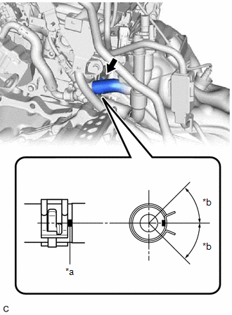
| (a) Connect the flow shutting valve (water by-pass hose assembly) to the water by-pass outlet sub-assembly and slide the clip to secure it. NOTICE:
|
|
(b) Install the wire harness clamp bracket with the bolt.
Torque:
13 N·m {133 kgf·cm, 10 ft·lbf}
(c) Connect the flow shutting valve (water by-pass hose assembly) with the bolt.
Torque:
19 N·m {194 kgf·cm, 14 ft·lbf}
(d) Connect the No. 2 water by-pass pipe sub-assembly with the bolt.
Torque:
19 N·m {194 kgf·cm, 14 ft·lbf}
(e) Connect the inlet heater hose connector to the flow shutting valve (water by-pass hose assembly).
NOTICE:
Check that there is no damage or foreign matter on the connecting parts of the water lines.
| (1) Align the protrusions of the inlet heater hose connector with the cutouts in the flow shutting valve (water by-pass hose assembly) and push them together until the inlet heater hose connector makes a "click" sound. |
|
.png)
(2) Push in the retainer.
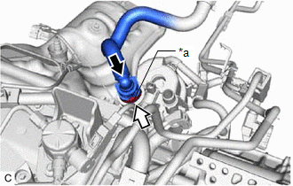
| *a | Retainer |
.png) | Push |
.png) | Push in |
(3) Check that the flow shutting valve (water by-pass hose assembly) and inlet heater hose connector are securely connected by pulling on them.
(f) Connect the outlet heater hose connector to the No. 2 water by-pass pipe sub-assembly.
NOTICE:
Check that there is no damage or foreign matter on the connecting parts of the water lines.
| (1) Align the protrusion of the No. 2 water by-pass pipe sub-assembly with the cutout in the outlet heater hose connector and push them together until the outlet heater hose connector makes a "click" sound. |
|
.png)
(2) Push in the retainer.
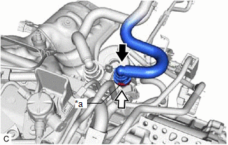
| *a | Retainer |
| | Push |
| | Push in |
(3) Check that the No. 2 water by-pass pipe sub-assembly and outlet heater hose connector are securely connected by pulling on them.
(g) Connect the flow shutting valve (water by-pass hose assembly) connector.
2. INSTALL INVERTER WITH CONVERTER ASSEMBLY
Click here .gif)
3. ADD ENGINE COOLANT (for Engine)
Click here
4. INSPECT FOR COOLANT LEAK (for Engine)
Click here
READ NEXT:
 Components
COMPONENTS ILLUSTRATION *1 FRONT WHEEL OPENING EXTENSION PAD LH *2 FRONT WHEEL OPENING EXTENSION PAD RH *3 NO. 1 ENGINE UNDER COVER *4 NO. 2 ENGINE UNDER COVER ASSEMBLY N*m
On-vehicle Inspection
ON-VEHICLE INSPECTION CAUTION / NOTICE / HINT CAUTION: Do not remove the radiator cap sub-assembly while the engine and radiator assembly are still hot. Pressurized, hot engine coolant and steam may b
SEE MORE:
ECU Power Source Circuit
DESCRIPTION If the power switch is on (IG), the hybrid vehicle control ECU applies current to the MREL terminal to turn the IGCT relay on. This supplies power to the +B1 and +B2 terminals. WIRING DIAGRAM CAUTION / NOTICE / HINT NOTICE: After turning the power switch off, waiting time may be require
ECM/PCM Power Relay Sense Circuit Intermittent (P06881F)
DESCRIPTION This DTC indicates that the hybrid vehicle control ECU detected an instantaneous interruption in +B power source voltage. DTC No. Detection Item DTC Detection Condition Trouble Area MIL Warning Indicate P06881F ECM/PCM Power Relay Sense Circuit Intermittent When the
