Lexus ES: Removal
REMOVAL
CAUTION / NOTICE / HINT
The necessary procedures (adjustment, calibration, initialization or registration) that must be performed after parts are removed and installed, or replaced during throttle body with motor assembly removal/installation are shown below.
Necessary Procedures After Parts Removed/Installed/Replaced| Replaced Part or Performed Procedure | Necessary Procedure | Effect/Inoperative Function when Necessary Procedure not Performed | Link |
|---|---|---|---|
| Inspection after repair |
| |
NOTICE:
This procedure includes the removal of small-head bolts. Refer to Small-Head Bolts of Basic Repair Hint to identify the small-head bolts.
Click here .gif)
PROCEDURE
1. DRAIN ENGINE COOLANT
Click here
2. REMOVE NO. 1 ENGINE COVER SUB-ASSEMBLY
Click here
3. REMOVE AIR CLEANER CAP WITH AIR CLEANER HOSE
| (a) Disconnect the mass air flow meter sub-assembly connector. |
|
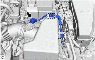
(b) Disengage the 2 wire harness clamps.
| (c) Disconnect the vacuum hose from the air cleaner hose. |
|
(d) Slide the clip and disconnect the No. 2 ventilation hose from the cylinder head cover sub-assembly.
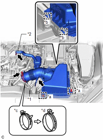
(e) Disengage the 2 air cleaner cap clamps.
(f) Disengage the 2 guides to separate the air cleaner cap sub-assembly from the air cleaner case sub-assembly.
(g) Lock the hose clip and remove the air cleaner cap with air cleaner hose from the throttle body with motor assembly.
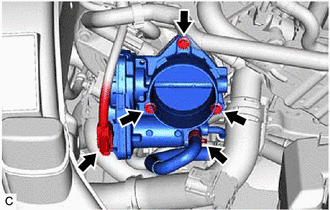
4. REMOVE THROTTLE BODY WITH MOTOR ASSEMBLY
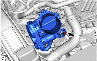
| (a) Disconnect the throttle body with motor assembly connector. |
|
(b) Slide the clip and disconnect the No. 6 water by-pass hose from the throttle body with motor assembly.
(c) Using an 8 mm socket wrench, remove the 3 bolts and separate the throttle body with motor assembly from the intake manifold.
| (d) Slide the clip and disconnect the No. 5 water by-pass hose to remove the throttle body with motor assembly. NOTICE: If the throttle body with motor assembly has been struck or dropped, replace it. |
|
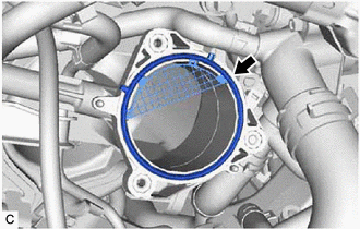
5. REMOVE THROTTLE BODY GASKET
| (a) Remove the throttle body gasket from the intake manifold. |
|
READ NEXT:
 Inspection
INSPECTION PROCEDURE 1. INSPECT THROTTLE BODY WITH MOTOR ASSEMBLY (a) Measure the resistance according to the value(s) in the table below. Standard Resistance: Tester Connection Condition S
Installation
INSTALLATION CAUTION / NOTICE / HINT NOTICE: This procedure includes the installation of small-head bolts. Refer to Small-Head Bolts of Basic Repair Hint to identify the small-head bolts. Click here
SEE MORE:
Cursor or Map Rotates when Vehicle Stopped
PROCEDURE 1. CHECK CONDITION (a) Check with the customer if the vehicle has been turned by a turntable. OK: Vehicle has not been turned by a turntable. HINT: If the vehicle is turned on a turntable with the power switch on (IG), the system may store the angular velocity. As a result, th
Hydraulic Control System Malfunction (C1214)
DESCRIPTION The skid control ECU (brake booster with master cylinder assembly) controls braking force according to the hybrid control system regenerative braking force and provides the hydraulic pressure necessary for operating the master cylinder and each wheel cylinder according to the servo press
