Lexus ES: Installation
INSTALLATION
CAUTION / NOTICE / HINT
NOTICE:
This procedure includes the installation of small-head bolts. Refer to Small-Head Bolts of Basic Repair Hint to identify the small-head bolts.
Click here .gif)
PROCEDURE
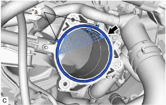
1. INSTALL THROTTLE BODY GASKET
| (a) Install a new throttle body gasket to the intake manifold with the protrusions of the throttle body gasket oriented as shown in the illustration. |
|
2. INSTALL THROTTLE BODY WITH MOTOR ASSEMBLY
HINT:
Perform "Inspection After Repair" after replacing the throttle body with motor assembly.
Click here
| (a) Connect the No. 5 water by-pass hose to the throttle body with motor assembly and slide the clip to secure it. NOTICE:
|
|
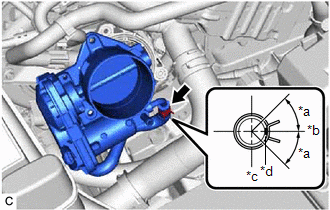
| (b) Using an 8 mm socket wrench, install the throttle body with motor assembly to the intake manifold with the 3 bolts. Torque: 10 N·m {102 kgf·cm, 7 ft·lbf} |
|
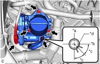
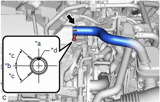
(c) Connect the No. 6 water by-pass hose to the throttle body with motor assembly and slide the clip to secure it.
NOTICE:
Make sure to position the clip as shown in the illustration.
(d) Connect the throttle body with motor assembly connector.
3. INSTALL AIR CLEANER CAP WITH AIR CLEANER HOSE
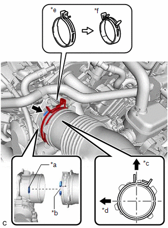
| (a) Install the air cleaner cap with air cleaner hose to the throttle body with motor assembly and unlock the hose clip to secure it as shown in the illustration. NOTICE: Align the cutout of the air cleaner hose with the protrusion of the throttle body with motor assembly. |
|
(b) Engage the 2 guides to install the air cleaner cap sub-assembly to the air cleaner case sub-assembly.
(c) Engage the 2 air cleaner cap clamps.
| (d) Connect the No. 2 ventilation hose to the cylinder head cover sub-assembly and slide the clip to secure it. NOTICE: Make sure to position the clip as shown in the illustration. |
|
(e) Connect the vacuum hose to the air cleaner hose.
(f) Engage the 2 wire harness clamps.
(g) Connect the mass air flow meter sub-assembly connector.
4. INSTALL NO. 1 ENGINE COVER SUB-ASSEMBLY
Click here
5. ADD ENGINE COOLANT
Click here
6. INSPECT FOR COOLANT LEAK
Click here
7. PERFORM INITIALIZATION
NOTICE:
- Be sure to perform this procedure after removing and reinstalling the throttle body with motor assembly or any throttle body with motor assembly components.
- Perform the following procedure after replacing the throttle body with motor assembly or any throttle body with motor assembly components. The following procedure should also be performed if the throttle body with motor assembly is cleaned.
(a) Connect the Techstream to the DLC3.
(b) Turn the engine switch on (IG).
(c) Turn the Techstream on.
(d) Clear the DTCs.
Powertrain > Engine > Clear DTCs(e) Perform "Inspection After Repair".
Click here
(f) Start the engine and check that the MIL is not illuminated. After the engine is warmed up, check that the idle speed is within the specified range with the A/C switch off.
Standard Idle Speed:
600 to 700 rpm
NOTICE:
- Be sure to perform this step with all accessories off.
- Make sure that the shift lever is in P or N.
(g) Enter the following menus: Powertrain / Engine / Data List / Throttle Position Sensor No.1 Voltage %.
Powertrain > Engine > Data List| Tester Display |
|---|
| Throttle Position Sensor No.1 Voltage % |
(h) According to the display on the Techstream, read the Data List while fully depressing the accelerator pedal and check that the value is 60% or higher.
(i) Perform a road test and confirm that there are no abnormalities.
READ NEXT:
 Removal
REMOVAL PROCEDURE 1. REMOVE COOL AIR INTAKE DUCT SEAL Click here 2. REMOVE NO. 1 ENGINE COVER SUB-ASSEMBLY Click here 3. REMOVE INLET AIR CLEANER ASSEMBLY Click here 4. REMOVE AIR CLEANER ASS
Inspection
INSPECTION PROCEDURE 1. INSPECT VACUUM SWITCHING VALVE (for Active Control Engine Mount System) (a) Measure the resistance. (1) Measure the resistance according to the value(s) in the table below.
SEE MORE:
Indicator (Green) Circuit Short to Ground (B157111,B157113)
DESCRIPTION This DTC is set when the DCM (telematics transceiver) detects an open or short in the manual (SOS) switch green indicator circuit of the manual (SOS) switch. The manual (SOS) switch green indicator illuminates after the engine switch is turned on (IG). If the safety connect system is not
Freeze Frame Data
FREEZE FRAME DATA FREEZE FRAME DATA HINT: The hybrid vehicle control ECU records vehicle and driving condition information as freeze frame data the moment a DTC is stored. It can be used for estimating or duplicating the vehicle conditions that were present when the malfunction occurred. (a) Connect
