Lexus ES: Removal
REMOVAL
CAUTION / NOTICE / HINT
The necessary procedures (adjustment, calibration, initialization or registration) that must be performed after parts are removed and installed, or replaced during air fuel ratio sensor removal/installation are shown below.
Necessary Procedures After Parts Removed/Installed/Replaced| Replaced Part or Performed Procedure | Necessary Procedure | Effect/Inoperative Function when Necessary Procedure not Performed | Link |
|---|---|---|---|
| Inspection after repair |
| |
PROCEDURE
1. REMOVE NO. 1 ENGINE COVER SUB-ASSEMBLY
Click here .gif)
2. REMOVE AIR FUEL RATIO SENSOR
CAUTION:
To prevent burns, do not touch the engine, exhaust manifold or other high temperature components while the engine is hot.
.png)
| (a) Disengage the 3 wire harness clamps. |
|
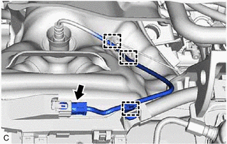
(b) Disconnect the air fuel ratio sensor connector.
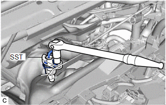
| (c) Using SST, remove the air fuel ratio sensor from the exhaust manifold (TWC: Front Catalyst). SST: 09224-00012 NOTICE: If the air fuel ratio sensor has been struck or dropped, replace it. |
|
READ NEXT:
 Inspection
INSPECTION PROCEDURE 1. INSPECT AIR FUEL RATIO SENSOR (a) Measure the resistance according to the value(s) in the table below. Standard Resistance: Tester Connection Condition Specified Con
Installation
INSTALLATION PROCEDURE 1. INSTALL AIR FUEL RATIO SENSOR HINT: Perform "Inspection After Repair" after replacing the air fuel ratio sensor. Click here (a) Using SST, install the air fuel ratio sen
SEE MORE:
Power Window Motor Malfunction (B2311)
DESCRIPTION The power window regulator motor assemblies are operated by the multiplex network master switch assembly, power window regulator switch assembly or rear power window regulator switch assemblies. The power window regulator motor assemblies have motor, regulator and ECU functions. This DTC
How To Proceed With Troubleshooting
CAUTION / NOTICE / HINT HINT:
Use the following procedure to troubleshoot the power mirror control system (w/o Memory).
*: Use the Techstream.
PROCEDURE 1. VEHICLE BROUGHT TO WORKSHOP
NEXT 2. CUSTOMER PROBLEM ANALYSIS HINT:
In troubleshooting, confirm th
