Lexus ES: On-vehicle Inspection
ON-VEHICLE INSPECTION
PROCEDURE
1. INSPECT WINDSHIELD WIPER MOTOR ASSEMBLY
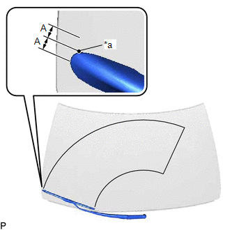
| (a) for RH Side (1) Operate the windshield wiper motor assembly. (2) Stop the windshield wiper motor assembly operation. (3) Check the automatic stop (park) position. HINT: After the front wiper motor is stopped, check the automatic stop position after lifting the wiper blade 2 times. Standard Clearance:
OK: The front wiper stops at the position shown in the illustration. |
|
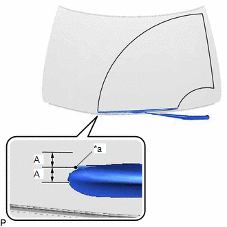
| (b) for LH Side (1) Operate the windshield wiper motor assembly. (2) Stop the windshield wiper motor assembly operation. (3) Check the automatic stop (park) position. HINT: After the front wiper motor is stopped, check the automatic stop position after lifting the wiper blade 2 times. Standard Clearance:
OK: The front wiper stops at the position shown in the illustration. |
|
READ NEXT:
 Removal
REMOVAL CAUTION / NOTICE / HINT NOTICE: Make sure to hold the front wiper arm while lifting it, as lifting the front wiper arm by the front wiper blade may damage or deform the front wiper blade. PROC
Inspection
INSPECTION CAUTION / NOTICE / HINT CAUTION: Be careful so that fingers and clothing do not get caught in the moving parts when performing this test. PROCEDURE 1. INSPECT WINDSHIELD WIPER MOTOR ASSEMBL
Installation
INSTALLATION CAUTION / NOTICE / HINT NOTICE: Make sure to hold the front wiper arm while lifting it, as lifting the front wiper arm by the front wiper blade may damage or deform the front wiper blade.
SEE MORE:
Torque Converter Clutch Pressure Control Solenoid Control Circuit Short to Ground or Open (P275614)
DESCRIPTION Refer to DTC P275612. Click here DTC No. Detection Item DTC Detection Condition Trouble Area MIL Memory Note P275614 Torque Converter Clutch Pressure Control Solenoid Control Circuit Short to Ground or Open While the vehicle is being driven, a short to ground or
EVAP System
RELATED DTCS DTC No. Monitoring Item Link P043E00 Reference orifice low flow P043F00 Reference orifice high flow P04417E Purge VSV stuck open P04417F Purge VSV stuck closed P04419C Insufficient purge flow P045011 Canister pressure sensor (buil
