Lexus ES: Installation
INSTALLATION
PROCEDURE
1. INSTALL FRONT ENGINE MOUNTING INSULATOR
(a) Install the stay to the front engine mounting insulator with the nut.
Torque:
6.0 N·m {61 kgf·cm, 53 in·lbf}
(b) Install the front engine mounting insulator to the front frame assembly with the 3 nuts.
Torque:
72 N·m {734 kgf·cm, 53 ft·lbf}
| (c) Install the front engine mounting bracket to the transaxle housing with the 3 bolts. Torque: Bolt (A), (B) and (C) : 42 N·m {428 kgf·cm, 31 ft·lbf} NOTICE: Temporarily tighten the bolt (A), and then fully tighten the 3 bolts in the order of (B), (C) and (A). |
|
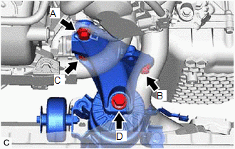
(d) Install the front engine mounting bracket to the front engine mounting insulator with the bolt.
Torque:
Bolt (D) :
72 N·m {734 kgf·cm, 53 ft·lbf}
(e) Install the vacuum hose to the front engine mounting insulator.
(f) Engage the 2 clamps to install the vacuum hoses to the front engine mounting insulator.
(g) Install the No. 1 radiator bracket to the front engine mounting bracket with the bolt.
Torque:
19 N·m {194 kgf·cm, 14 ft·lbf}
(h) Engage the 4 clamps to install the radiator hose, vacuum hoses and No. 2 engine wire to the No. 1 radiator bracket.
2. INSTALL SUSPENSION TOWER DAMPER (w/ Performance Damper)
Click here .gif)
3. INSTALL NO. 2 ENGINE UNDER COVER ASSEMBLY
Click here
4. INSTALL NO. 1 ENGINE UNDER COVER
Click here
5. INSTALL FRONT WHEEL OPENING EXTENSION PAD LH
Click here
6. INSTALL FRONT WHEEL OPENING EXTENSION PAD RH
Click here
7. INSTALL VACUUM SWITCHING VALVE (for Active Control Engine Mount System)
Click here
READ NEXT:
 Removal
REMOVAL CAUTION / NOTICE / HINT The necessary procedures (adjustment, calibration, initialization or registration) that must be performed after parts are removed and installed, or replaced during air
Inspection
INSPECTION PROCEDURE 1. INSPECT AIR FUEL RATIO SENSOR (a) Measure the resistance according to the value(s) in the table below. Standard Resistance: Tester Connection Condition Specified Con
SEE MORE:
Problem Symptoms Table
PROBLEM SYMPTOMS TABLE NOTICE:
Before checking parts for malfunctions, check that the audio system operates normally.
Use the table below to help determine the cause of problem symptoms. If multiple suspected areas are listed, the potential causes of the symptoms are listed in order of probabil
Hybrid/EV Battery Positive and Negative Contactor Actuator Stuck Closed (P0AA073)
DTC SUMMARY MALFUNCTION DESCRIPTION The hybrid vehicle control ECU detects a stuck closed malfunction of a system main relay on the positive (+) terminal side and negative (-) terminal side of the HV battery. The cause of this malfunction may be one of the following: Inverter voltage sensor (VH) in
