Lexus ES: Removal
REMOVAL
CAUTION / NOTICE / HINT
The necessary procedures (adjustment, calibration, initialization or registration) that must be performed after parts are removed and installed, or replaced during PCV valve (ventilation valve sub-assembly) removal/installation are shown below.
Necessary Procedures After Parts Removed/Installed/Replaced| Replaced Part or Performed Procedure | Necessary Procedures | Effect/Inoperative Function when Necessary Procedure not Performed | Link |
|---|---|---|---|
| Inspection After Repair |
| |
NOTICE:
This procedure includes the removal of small-head bolts. Refer to Small-Head Bolts of Basic Repair Hint to identify the small-head bolts.
Click here .gif)
PROCEDURE
1. REMOVE INTAKE MANIFOLD
Click here
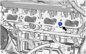
2. REMOVE PCV VALVE (VENTILATION VALVE SUB-ASSEMBLY)
| (a) Remove the PCV valve (ventilation valve sub-assembly) from the cylinder head sub-assembly. |
|
READ NEXT:
 Inspection
INSPECTION PROCEDURE 1. INSPECT PCV VALVE (VENTILATION VALVE SUB-ASSEMBLY) (a) Install a hose to the PCV valve (ventilation valve sub-assembly). (b) Check PCV valve (ventilation valve sub-assembly) op
Installation
INSTALLATION CAUTION / NOTICE / HINT NOTICE: This procedure includes the installation of small-head bolts. Refer to Small-Head Bolts of Basic Repair Hint to identify the small-head bolts. Click here
Purge Valve
ComponentsCOMPONENTS ILLUSTRATION *1 PURGE VALVE (PURGE VSV) *2 NO. 1 FUEL VAPOR FEED HOSE *3 NO. 2 FUEL VAPOR FEED HOSE - - N*m (kgf*cm, ft.*lbf): Specified torque - -
SEE MORE:
Components
COMPONENTS ILLUSTRATION *1 FRONT FENDER APRON SEAL LH *2 FRONT FENDER APRON SEAL RH *3 FRONT WHEEL OPENING EXTENSION PAD LH *4 FRONT WHEEL OPENING EXTENSION PAD RH *5 NO. 1 ENGINE UNDER COVER *6 NO. 2 ENGINE UNDER COVER N*m (kgf*cm, ft.*lbf): Specified torque -
Stop Switch Circuit Malfunction (C164E)
DESCRIPTION When a stop light switch assembly circuit malfunction signal sent from the electronically controlled brake system is detected by the clearance warning ECU assembly, DTC C164E is stored. DTC No. Detection Item DTC Detection Condition Trouble Area C164E Stop Switch Circuit M
