Lexus ES: Inspection
INSPECTION
PROCEDURE
1. INSPECT PCV VALVE (VENTILATION VALVE SUB-ASSEMBLY)
(a) Install a hose to the PCV valve (ventilation valve sub-assembly).
(b) Check PCV valve (ventilation valve sub-assembly) operation.
(1) Blow air into the cylinder head sub-assembly side, and check that air passes through easily.
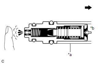
| *a | Hose |
| *b | Air |
.png) | Cylinder Head Sub-assembly Side |
CAUTION:
Do not suck air through the valve.
Petroleum substances inside the valve are hazardous to your health.
If the result is not as specified, replace the PCV valve (ventilation valve sub-assembly).
(2) Blow air into the intake manifold side, and check that air passes through with difficulty.
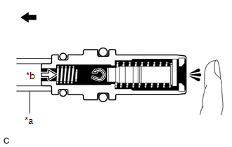
| *a | Hose |
| *b | Air |
| | Intake Manifold Side |
CAUTION:
Do not suck air through the valve.
Petroleum substances inside the valve are hazardous to your health.
If the result is not as specified, replace the PCV valve (ventilation valve sub-assembly).
(c) Remove the hose from the PCV valve (ventilation valve sub-assembly).
READ NEXT:
 Installation
INSTALLATION CAUTION / NOTICE / HINT NOTICE: This procedure includes the installation of small-head bolts. Refer to Small-Head Bolts of Basic Repair Hint to identify the small-head bolts. Click here
Purge Valve
ComponentsCOMPONENTS ILLUSTRATION *1 PURGE VALVE (PURGE VSV) *2 NO. 1 FUEL VAPOR FEED HOSE *3 NO. 2 FUEL VAPOR FEED HOSE - - N*m (kgf*cm, ft.*lbf): Specified torque - -
Vacuum Sensor
ComponentsCOMPONENTS ILLUSTRATION *1 E.F.I. VACUUM SENSOR ASSEMBLY (MANIFOLD ABSOLUTE PRESSURE SENSOR) *2 VACUUM HOSE N*m (kgf*cm, ft.*lbf): Specified torque - - RemovalREMOV
SEE MORE:
Installation
INSTALLATION PROCEDURE 1. INSTALL FUEL PIPE PLUG SUB-ASSEMBLY (a) Install a new O-ring, No. 1 fuel injector back-up ring, No. 2 fuel injector back-up ring and No. 3 fuel injector back-up ring to the fuel pipe plug sub-assembly as shown in the illustration. *1 Fuel Pipe Plug Sub-assembly *2
Headlight aim
Vertical movement adjusting
bolts
Vehicles with single-beam headlights
Adjustment bolt A
Adjustment bolt B
Vehicles with triple-beam headlights
Adjustment bolt A
Adjustment bolt B
Before checking the headlight
aim
Make sure the vehicle has a full tank
of gasoline and t
