Lexus ES: Removal
REMOVAL
CAUTION / NOTICE / HINT
The necessary procedures (adjustment, calibration, initialization or registration) that must be performed after parts are removed and installed, or replaced during starter assembly removal/installation are shown below.
Necessary Procedures After Parts Removed/Installed/Replaced| Replaced Part or Performed Procedure | Necessary Procedure | Effect/Inoperative Function when Necessary Procedure not Performed | Link |
|---|---|---|---|
|
*: When performing learning using the Techstream.
Click here | |||
| Battery terminal is disconnected/reconnected | Perform steering sensor zero point calibration | Lane Control System (for Gasoline Model) | |
| Pre-collision System (for Gasoline Model) | |||
| Parking Support Brake System (for Gasoline Model)* | |||
| Lighting System (for Gasoline Model) | |||
| Memorize steering angle neutral point | Parking Assist Monitor System (for Gasoline Model) | | |
| Panoramic View Monitor System (for Gasoline Model) | | ||
| Initialize power trunk lid system | Power Trunk Lid System (for Gasoline Model) | | |
NOTICE:
- After the engine switch is turned off, the radio receiver assembly records various types of memory and settings. As a result, after turning the engine switch off, make sure to wait at least 85 seconds before disconnecting the cable from the negative (-) battery terminal. (for Audio and Visual System)
- After the engine switch is turned off, the radio receiver assembly records various types of memory and settings. As a result, after turning the engine switch off, make sure to wait at least 85 seconds before disconnecting the cable from the negative (-) battery terminal. (for Navigation System)
PROCEDURE
1. PRECAUTION
NOTICE:
After turning the engine switch off, waiting time may be required before disconnecting the cable from the negative (-) battery terminal. Therefore, make sure to read the disconnecting the cable from the negative (-) battery terminal notices before proceeding with work.
2. REMOVE BATTERY
Click here .gif)
3. REMOVE COOL AIR INTAKE DUCT SEAL
Click here
4. REMOVE V-BANK COVER SUB-ASSEMBLY
Click here
5. REMOVE INLET AIR CLEANER ASSEMBLY
Click here
6. REMOVE AIR CLEANER ASSEMBLY WITH AIR CLEANER HOSE
Click here
7. REMOVE ECM
Click here
8. REMOVE BATTERY CLAMP SUB-ASSEMBLY
Click here
9. REMOVE STARTER ASSEMBLY
| (a) Disconnect the starter assembly connector. |
|
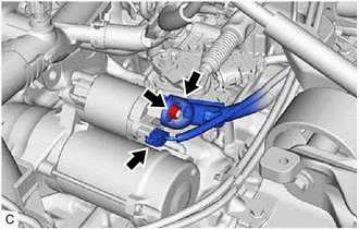
(b) Open the terminal cap.
(c) Remove the nut and disconnect the engine wire from the terminal 30.
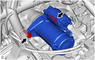
| (d) Remove the 2 bolts and starter assembly. |
|
READ NEXT:
 Inspection
INSPECTION PROCEDURE 1. INSPECT STARTER ASSEMBLY CAUTION: As a large electric current passes through the cable during this inspection, a thick cable must be used. If not, the cable may become hot and
Reassembly
REASSEMBLY PROCEDURE 1. INSTALL PLANETARY GEAR (a) Apply high-temperature grease to the 3 planetary gears, 3 planetary gear shafts and repair service starter kit. High-temperature Grease (b)
Installation
INSTALLATION PROCEDURE 1. INSTALL STARTER ASSEMBLY (a) Install the starter assembly with the 2 bolts. Torque: 46 N·m {469 kgf·cm, 34 ft·lbf} (b) Connect the engine wire to the terminal 30 with the
SEE MORE:
Open or Short in Steering Angle Sensor +B (C1625)
DESCRIPTION This DTC is stored if the clearance warning ECU assembly receives a signal via CAN communication from the steering sensor that indicates a power supply problem. DTC No. Detection Item DTC Detection Condition Trouble Area C1625 Open or Short in Steering Angle Sensor +B Op
Fail-safe Chart
FAIL-SAFE CHART FAIL-SAFE FUNCTION (a) When a malfunction occurs in the lane control system, a message will be displayed on the multi-information display and, depending on the malfunction, functions of the lane control system will be disabled. Warning Message Cause Fail-safe Operation Condi
