Lexus ES: Camshaft Position Sensor "A" Circuit Bank 1 or Single Sensor (P034000,P034031)
DESCRIPTION
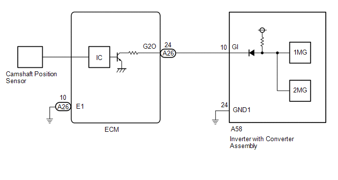
If the cam position signal pulse sent from the ECM via a direct line is abnormal, the motor generator control ECU (MG ECU) (built into the inverter with converter assembly) stores DTC P034000 or P034031.
| DTC No. | Detection Item | DTC Detection Condition | Trouble Area | MIL | Warning Indicate |
|---|---|---|---|---|---|
| P034000 | Camshaft Position Sensor "A" Circuit Bank 1 or Single Sensor | GI signal (camshaft position sensor) is not input for 2 sec. or more while the engine is running* (1 trip detection logic) |
| Does not come on | Master Warning Light: Comes on |
| P034031 | Camshaft Position Sensor "A" Circuit Bank 1 or Single Sensor No Signal | GI signal (camshaft position sensor) is not input for 2 sec. or more while the engine is running* (1 trip detection logic) |
| Does not come on | Master Warning Light: Comes on |
HINT:
*: When this DTC is stored, vibration may occur when the engine is stopped.
Related Data List| DTC No. | Data List |
|---|---|
| P034000 P034031 |
|
CONFIRMATION DRIVING PATTERN
HINT:
After repair has been completed, clear the DTC and then check that the vehicle has returned to normal by performing the following All Readiness check procedure.
Click here .gif)
- Connect the Techstream to the DLC3.
- Turn the power switch on (IG) and turn the Techstream on.
- Clear the DTCs (even if no DTCs are stored, perform the clear DTC procedure).
- Turn the power switch off and wait for 2 minutes or more.
- Turn the power switch on (IG) and turn the Techstream on.
- Turn the power switch on (READY).
- With the vehicle stopped, move the shift lever to P.
- Depress the accelerator pedal to start the engine.
-
Depress the accelerator pedal and maintain the engine speed at 1000 rpm or more for 5 seconds or more.
NOTICE:
As the state of charge of the HV battery may be low after driving in fail-safe mode, it will automatically be charged for 5 to 10 minutes with power switch on (READY) after repairs have been performed.
- Enter the following menus: Powertrain / Motor Generator / Utility / All Readiness.
-
Check the DTC judgment result.
HINT:
- If the judgment result shows NORMAL, the system is normal.
- If the judgment result shows ABNORMAL, the system has a malfunction.
- If the judgment result shows INCOMPLETE or N/A, perform driving pattern again.
WIRING DIAGRAM
CAUTION / NOTICE / HINT
CAUTION:
.png)
-
Before the following operations are conducted, take precautions to prevent electric shock by turning the power switch off, wearing insulated gloves, and removing the service plug grip from HV battery.
- Inspecting the high-voltage system
- Disconnecting the low voltage connector of the inverter with converter assembly
- Disconnecting the low voltage connector of the HV battery
-
To prevent electric shock, make sure to remove the service plug grip to cut off the high voltage circuit before servicing the vehicle.

-
After removing the service plug grip from the HV battery, put it in your pocket to prevent other technicians from accidentally reconnecting it while you are working on the high-voltage system.

-
After removing the service plug grip, wait for at least 10 minutes before touching any of the high-voltage connectors or terminals. After waiting for 10 minutes, check the voltage at the terminals in the inspection point in the inverter with converter assembly. The voltage should be 0 V before beginning work.
Click here
HINT:
Waiting for at least 10 minutes is required to discharge the high-voltage capacitor inside the inverter with converter assembly.
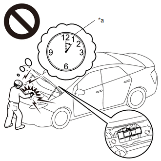
*a
Without waiting for 10 minutes
NOTICE:
After turning the power switch off, waiting time may be required before disconnecting the cable from the negative (-) auxiliary battery terminal. Therefore, make sure to read the disconnecting the cable from the negative (-) auxiliary battery terminal notices before proceeding with work.
Click here
PROCEDURE
| 1. | CHECK DTC OUTPUT (ENGINE) |
(a) Connect the Techstream to the DLC3.
(b) Turn the power switch on (IG).
(c) Enter the following menus: Powertrain / Engine / Trouble Codes.
(d) Check for DTCs.
Powertrain > Engine > Trouble Codes| Result | Proceed to |
|---|---|
| SFI system DTCs are not output. | A |
| Any of the following DTCs are also output. | B |
| Relevant DTC | |
|---|---|
| P034011 | Camshaft Position Sensor "A" Bank 1 or Single Sensor Circuit Short to Ground |
| P034015 | Camshaft Position Sensor "A" Bank 1 or Single Sensor Circuit Short to Battery or Open |
| P03402A | Camshaft Position Sensor "A" Bank 1 or Single Sensor Signal Stuck in Range |
| P034031 | Camshaft Position Sensor "A" Bank 1 or Single Sensor No Signal |
(e) Turn the power switch off.
| B | .gif) | GO TO DTC CHART (SFI SYSTEM) |
|
.gif)
| 2. | CHECK DTC OUTPUT (MOTOR GENERATOR CONTROL) |
(a) Connect the Techstream to the DLC3.
(b) Turn the power switch on (IG).
(c) Enter the following menus: Powertrain / Motor Generator / Trouble Codes.
(d) Check for DTCs.
Powertrain > Motor Generator > Trouble Codes| Result | Proceed to |
|---|---|
| None of the following DTCs are output. | A |
| Any of the following DTCs are also output. | B |
| Relevant DTC | |
|---|---|
| P06B01C | Generator Control Module Position Sensor REF Power Source Circuit Voltage Out of Range |
| P06D61C | Generator Control Module Offset Power Circuit Voltage Out of Range |
| P0A1B1F | Generator Control Module Circuit Intermittent |
| P1C2B49 | Drive Motor "A" Control Module A/D Converter Circuit Internal Electronic Failure |
| P1C2B1C | Drive Motor "A" Control Module A/D Converter Circuit Voltage Out of Range |
| P1CAD49 | Drive Motor "A" Position Sensor Internal Electronic Failure |
| P1CB038 | Drive Motor "A" Position Sensor REF Signal Frequency Incorrect |
| P313487 | Communication Error from Drive Motor "A" to Generator Missing Message |
| P313483 | Communication Error from Drive Motor "A" to Generator Value of Signal Protection Calculation Incorrect |
| P313486 | Communication Error from Drive Motor "A" to Generator Signal Invalid |
HINT:
P034000 or P034031 may be stored due to a malfunction which also causes the DTCs in the preceding table to be stored. In this case, first troubleshoot the output DTCs in the preceding table. Then, perform a test to attempt to reproduce the problems, and check that no DTCs are output.
(e) Turn the power switch off.
| B | | GO TO DTC CHART (MOTOR GENERATOR CONTROL SYSTEM) |
|
| 3. | CHECK CONNECTOR CONNECTION CONDITION (INVERTER WITH CONVERTER ASSEMBLY CONNECTOR) |
Click here
| Result | Proceed to |
|---|---|
| OK | A |
| NG (The connector is not connected securely.) | B |
| NG (The terminals are not making secure contact or are deformed, or water or foreign matter exists in the connector.) | C |
| B | | CONNECT SECURELY |
| C | | REPAIR OR REPLACE HARNESS OR CONNECTOR |
|
| 4. | CHECK CONNECTOR CONNECTION CONDITION (ECM CONNECTOR) |
Click here
| NG | | CONNECT SECURELY |
|
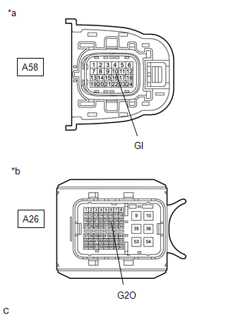
| 5. | CHECK HARNESS AND CONNECTOR (INVERTER WITH CONVERTER ASSEMBLY - ECM) |
CAUTION:
Be sure to wear insulated gloves.
(a) Check that the service plug grip is not installed.
NOTICE:
After removing the service plug grip, do not turn the power switch on (READY), unless instructed by the repair manual because this may cause a malfunction.
(b) Disconnect the A58 inverter with converter assembly connector.
(c) Disconnect the A26 ECM connector.
(d) Connect the cable to the negative (-) auxiliary battery terminal.
(e) Turn the power switch on (IG).
| (f) Measure the voltage according to the value(s) in the table below. Standard Voltage:
NOTICE: Turning the power switch on (IG) with the inverter with converter assembly connector and ECM connector disconnected causes other DTCs to be stored. Clear the DTCs after performing this inspection. |
|
(g) Turn the power switch off.
(h) Measure the resistance according to the value(s) in the table below.
Standard Resistance (Check for Open):
| Tester Connection | Condition | Specified Condition |
|---|---|---|
| A58-10 (GI) - A26-24 (G2O) | Power switch off | Below 1 Ω |
Standard Resistance (Check for Short):
| Tester Connection | Condition | Specified Condition |
|---|---|---|
| A58-10 (GI) or A26-24 (G2O) - Body ground and other terminals | Power switch off | 10 kΩ or higher |
(i) Disconnect the cable from the negative (-) auxiliary battery terminal.
(j) Reconnect the A26 ECM connector.
(k) Reconnect the A58 inverter with converter assembly connector.
| NG | | REPAIR OR REPLACE HARNESS OR CONNECTOR |
|
| 6. | CHECK ECM |
(a) Disconnect the A26 ECM connector.
(b) Measure the resistance according to the value(s) in the table below.
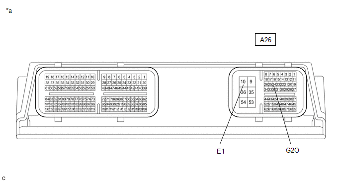
| *a | Component without harness connected (ECM) | - | - |
Standard Resistance:
| Tester Connection | Condition | Specified Condition |
|---|---|---|
| A26-24 (G2O) - A26-10 (E1) | Power switch off | 10 kΩ or higher |
(c) Reconnect the A26 ECM connector.
| OK | | REFER TO REPLACE INVERTER WITH CONVERTER ASSEMBLY PARTS |
| NG | | REPLACE ECM |
READ NEXT:
 Generator Control Module(EEPROM Learning Value) Calibration / Parameter Memory Failure (P062F46)
DESCRIPTION The inverter with converter assembly monitors its internal operation and will store this DTC if it detects a malfunction of its EEPROM. DTC No. Detection Item DTC Detection Conditio
Generator Control Module Position Sensor REF Power Source Circuit Voltage Out of Range (P06B01C,...,P313487)
DESCRIPTION The motor generator control ECU (MG ECU), which is built into the inverter with converter assembly, monitors its internal operation and will store DTCs if it detects a malfunction. If any
Motor Electronics Coolant Temperature Sensor Circuit Short to Ground (P0A0011,P0A0015)
DESCRIPTION Refer to the description for DTC P0A001C. Click here DTC No. Detection Item DTC Detection Condition Trouble Area MIL Warning Indicate P0A0011 Motor Electronics Coolant
SEE MORE:
Installation
INSTALLATION PROCEDURE 1. INSTALL STUD BOLT HINT: If a stud bolt is deformed or its threads are damaged, replace it. (a) Using an E8 "TORX" socket wrench, install the 2 stud bolts to the exhaust manifold assembly LH (TWC: Front Catalyst). Torque: 19.5 N·m {199 kgf·cm, 14 ft·lbf} 2
Diagnostic Trouble Code Chart
DIAGNOSTIC TROUBLE CODE CHART Wiper and Washer System DTC No. Detection Item DTC Output from Link B1245 Lost Communication with Wiper ECU LIN Main Body B1279 Lost Communication with Humidity/Rain Sensor LIN Main Body B1370 ECU Malfunction Windshield wiper m
