Lexus ES: Removal
REMOVAL
CAUTION / NOTICE / HINT
The necessary procedures (adjustment, calibration, initialization or registration) that must be performed after parts are removed and installed, or replaced during timing chain cover assembly removal/installation are shown below.
Necessary Procedure After Parts Removed/Installed/Replaced| Replaced Part or Performed Procedure | Necessary Procedure | Effect/Inoperative Function when Necessary Procedure not Performed | Link |
|---|---|---|---|
| Battery terminal is disconnected/reconnected | Perform steering sensor zero point calibration | Lane Control System | |
| Pre-collision System | |||
| Parking Support Brake System*1 | |||
| Lighting System | |||
| Memorize steering angle neutral point | Parking Assist Monitor System | | |
| Panoramic View Monitor System | | ||
| Initialize power trunk lid system | Power Trunk Lid System | | |
| Replacement of ECM | Vehicle Identification Number (VIN) registration | MIL comes on | |
| ECU communication ID registration (Immobiliser system) | Engine start function | | |
| Inspection after repair |
| |
| Replacement of automatic transaxle assembly |
|
| for Initialization: for Registration: |
| Replacement of ECM (If transaxle compensation code read from ECM) |
| ||
| Replacement of ECM (If transaxle compensation code not read from ECM) |
| ||
| Replacement of ECM | Code registration (Smart access system with push-button start (for Start Function, Gasoline Model) |
| |
| Replacement of automatic transaxle fluid | ATF thermal degradation estimate reset | The value of the Data List item "ATF Thermal Degradation Estimate" is not estimated correctly | |
| Suspension, tires, etc. (The vehicle height changes because of suspension or tire replacement) | Rear television camera assembly optical axis adjustment (Back camera position setting) | Parking assist monitor system | for Initialization: for Calibration: |
| Perform headlight ECU sub-assembly LH initialization | Lighting system | | |
| Front wheel alignment adjustment |
|
| |
| Front television camera view adjustment | Panoramic View Monitor System | for Initialization for Calibration |
| Replacement of front bumper assembly |
|
| |
-
*1: When performing learning using the Techstream.
Click here
.gif)
- *2: Not necessary when ECM replaced with new one
NOTICE:
- After the engine switch is turned off, the radio receiver assembly records various types of memory and settings. As a result, after turning the engine switch off, make sure to wait at least 85 seconds before disconnecting the cable from the negative (-) battery terminal. (for Audio and Visual System)
- After the engine switch is turned off, the radio receiver assembly records various types of memory and settings. As a result, after turning the engine switch off, make sure to wait at least 85 seconds before disconnecting the cable from the negative (-) battery terminal. (for Navigation System)
PROCEDURE
1. REMOVE OIL PAN SUB-ASSEMBLY
Click here
2. REMOVE TIMING CHAIN CASE OIL SEAL
Click here
3. REMOVE TIMING CHAIN COVER ASSEMBLY
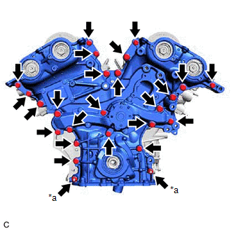
| (a) w/ Stud Bolt: (1) Remove the 23 bolts and 2 nuts shown in the illustration. |
|
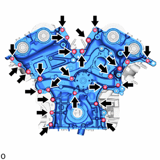
| (b) w/o Stud Bolt: (1) Remove the 25 bolts shown in the illustration. |
|
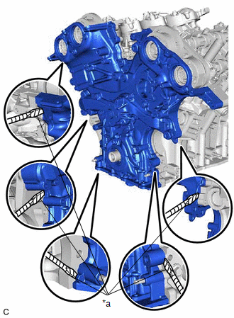
| (c) Remove the timing chain cover assembly by prying between the timing chain cover assembly and cylinder head sub-assembly or cylinder block sub-assembly with a screwdriver with its tip wrapped with protective tape. NOTICE: Be careful not to damage the contact surfaces of the cylinder head sub-assembly, cylinder block sub-assembly and timing chain cover assembly. |
|
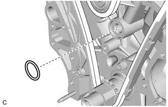
| (d) Remove the oil pump gasket from the cylinder block sub-assembly. |
|
READ NEXT:
 Disassembly
DISASSEMBLY PROCEDURE 1. REMOVE OIL PUMP RELIEF VALVE (a) Using a 27 mm socket wrench, remove the oil pump relief valve plug from the oil pump cover. (b) Remove the oil pump relief valv
Inspection
INSPECTION PROCEDURE 1. INSPECT OIL PUMP RELIEF VALVE (a) Coat the oil pump relief valve with engine oil and check that it falls smoothly into the valve hole by its own weight. HINT: If the oil pum
Reassembly
REASSEMBLY PROCEDURE 1. INSTALL OIL PUMP ROTOR SET (a) Coat the drive rotor and driven rotor with engine oil and place them into the timing chain cover assembly with the rotor marks facing up. Chec
SEE MORE:
Registration
REGISTRATION CAUTION / NOTICE / HINT NOTICE:
When the automatic transaxle assembly is replaced, the transaxle compensation code must be registered to the ECM (proceed to Procedure 1).
After the automatic transaxle assembly is installed, the Quick Response (QR) code label will be positioned where
Parts Location
PARTS LOCATION ILLUSTRATION *1 MILLIMETER WAVE RADAR SENSOR ASSEMBLY *2 FORWARD RECOGNITION CAMERA *3 HEADLIGHT ECU SUB-ASSEMBLY LH - - ILLUSTRATION *1 DLC3 *2 INSTRUMENT PANEL JUNCTION BLOCK ASSEMBLY - ECU-IG1 NO. 3 FUSE
