Lexus ES: Reassembly
REASSEMBLY
PROCEDURE
1. INSTALL OIL PUMP ROTOR SET
| (a) Coat the drive rotor and driven rotor with engine oil and place them into the timing chain cover assembly with the rotor marks facing up. Check that the rotors rotate smoothly. |
|
.png)
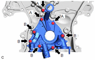
2. INSTALL OIL PUMP COVER
| (a) Install the oil pump cover to the timing chain cover assembly with the 8 bolts. Torque: 9.1 N·m {93 kgf·cm, 81 in·lbf} Bolt Length:
|
|
3. INSTALL OIL PUMP RELIEF VALVE
(a) Coat the oil pump relief valve with engine oil.
(b) Insert the oil pump relief valve and oil pump relief valve spring into the valve hole.
| (c) Using a 27 mm socket wrench, install the oil pump relief valve plug to the oil pump cover. Torque: 49 N·m {500 kgf·cm, 36 ft·lbf} |
|
.png)
READ NEXT:
 Installation
INSTALLATION PROCEDURE 1. INSTALL TIMING CHAIN COVER ASSEMBLY (a) Clean the contact surfaces of the engine assembly, and confirm that no oil, moisture, or other foreign matter is on the surfaces.
SEE MORE:
Airbag Signal Signal Plausibility Failure (B15C464)
DESCRIPTION If the DCM (telematics transceiver) detects an error in communication between the DCM (telematics transceiver) and the airbag ECU assembly as a result of the DCM (telematics transceiver) self check, this DTC will be set. DTC No. Detection Item DTC Detection Condition Trouble Are
How To Proceed With Troubleshooting
CAUTION / NOTICE / HINT HINT:
Use the following procedure to troubleshoot the window defogger system.
*: Use the Techstream.
PROCEDURE 1. VEHICLE BROUGHT TO WORKSHOP
NEXT 2. CUSTOMER PROBLEM ANALYSIS HINT:
In troubleshooting, confirm that the problem sym
