Lexus ES: Removal
REMOVAL
CAUTION / NOTICE / HINT
The necessary procedures (adjustment, calibration, initialization or registration) that must be performed after parts are removed and installed, or replaced during intake manifold removal/installation are shown below.
Necessary Procedures After Parts Removed/Installed/Replaced| Replaced Part or Performed Procedure | Necessary Procedure | Effect/Inoperative Function when Necessary Procedure not Performed | Link |
|---|---|---|---|
|
*: When performing learning using the Techstream.
Click here | |||
| Battery terminal is disconnected/reconnected | Perform steering sensor zero point calibration | Lane Control System (for Gasoline Model) | |
| Pre-collision System (for Gasoline Model) | |||
| Parking Support Brake System (for Gasoline Model)* | |||
| Lighting System (for Gasoline Model) | |||
| Memorize steering angle neutral point | Parking Assist Monitor System (for Gasoline Model) | | |
| Panoramic View Monitor System (for Gasoline Model) | | ||
| Initialize power trunk lid system | Power Trunk Lid System (for Gasoline Model) | | |
| Inspection after repair |
| |
NOTICE:
- After the engine switch is turned off, the radio receiver assembly records various types of memory and settings. As a result, after turning the engine switch off, make sure to wait at least 85 seconds before disconnecting the cable from the negative (-) battery terminal. (for Audio and Visual System)
- After the engine switch is turned off, the radio receiver assembly records various types of memory and settings. As a result, after turning the engine switch off, make sure to wait at least 85 seconds before disconnecting the cable from the negative (-) battery terminal. (for Navigation System)
PROCEDURE
1. PRECAUTION
NOTICE:
After turning the engine switch off, waiting time may be required before disconnecting the cable from the negative (-) battery terminal. Therefore, make sure to read the disconnecting the cable from the negative (-) battery terminal notices before proceeding with work.
2. DISCHARGE FUEL SYSTEM PRESSURE
Click here .gif)
3. DISCONNECT CABLE FROM NEGATIVE BATTERY TERMINAL
Click here
4. REMOVE COWL TOP VENTILATOR LOUVER SUB-ASSEMBLY
Click here
5. REMOVE FRONT CENTER UPPER SUSPENSION BRACE SUB-ASSEMBLY
Click here
6. REMOVE THROTTLE BODY WITH MOTOR ASSEMBLY
Click here
7. REMOVE V-BANK COVER SUB-ASSEMBLY
Click here
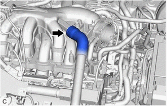
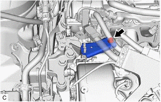
8. DISCONNECT VENTILATION HOSE
| (a) Slide the clip and disconnect the ventilation hose from the intake air surge tank assembly. |
|
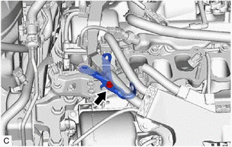
9. DISCONNECT PURGE VALVE (PURGE VSV)
| (a) Disconnect the No. 1 fuel vapor feed hose from the intake air surge tank assembly. |
|
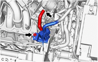
(b) Remove the bolt and disconnect the purge valve (purge VSV) from the intake air surge tank assembly.
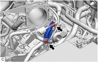
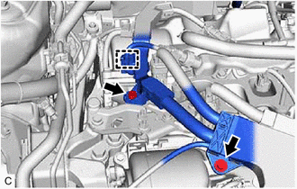
10. REMOVE NO. 2 SURGE TANK STAY
| (a) Remove the 2 bolts and No. 2 surge tank stay from the intake air surge tank assembly and camshaft housing RH. |
|
11. REMOVE INTAKE AIR SURGE TANK ASSEMBLY
| (a) Disconnect the vacuum switching valve (for ACIS) connector. |
|
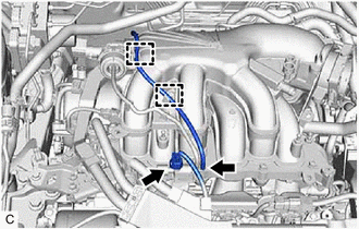
(b) Disconnect the vacuum hose sub-assembly from the vacuum switching valve (for ACIS).
(c) Disengage the 2 clamps to disconnect the vacuum hose sub-assembly from the intake air surge tank assembly.
| (d) Disengage the 2 clamps to disconnect the vacuum hose sub-assembly from the intake air surge tank assembly. |
|
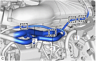
(e) Disengage the clamp to disconnect the vacuum hose from the intake air surge tank assembly.
(f) Disengage the clamp to disconnect the No. 2 air tube from the intake air surge tank assembly.
(g) Remove the 5 bolts, 2 nuts and intake air surge tank assembly from the intake manifold.
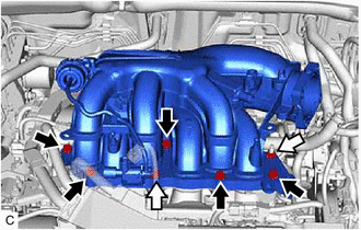
.png) | Bolt |
.png) | Nut |
(h) Remove the plug from the intake air surge tank assembly.
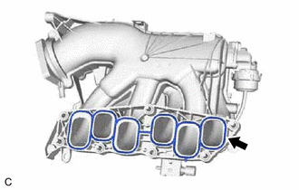
12. REMOVE AIR SURGE TANK TO INTAKE MANIFOLD GASKET
| (a) Remove the air surge tank to intake manifold gasket from the intake air surge tank assembly. |
|
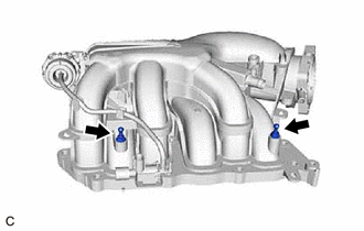
13. REMOVE NO. 1 V-BANK COVER BRACKET
HINT:
Perform this procedure only when replacement of the No. 1 V-bank cover bracket is necessary.
| (a) Remove the 2 No. 1 V-bank cover brackets from the intake air surge tank assembly. |
|
14. REMOVE NO. 2 ENGINE MOUNTING STAY RH
| (a) Remove the 2 bolts. |
|
(b) Disengage the wire harness clamp and disconnect the engine wire.
| (c) Remove the bolt and separate the wire harness clamp bracket from the No. 2 engine mounting stay RH. |
|
(d) Remove the bolt, 2 nuts and No. 2 engine mounting stay RH from the engine mounting insulator sub-assembly RH.

| | Bolt |
| | Nut |
| (e) Remove the bolt and No. 2 engine mounting stay RH from the intake manifold and front No. 1 engine mounting bracket LH. |
|
15. DISCONNECT FUEL TUBE SUB-ASSEMBLY
Click here
16. REMOVE FUEL DELIVERY PIPE WITH SENSOR ASSEMBLY
Click here
17. REMOVE NO. 1 DELIVERY PIPE SPACER
Click here
18. REMOVE INJECTOR VIBRATION INSULATOR
Click here
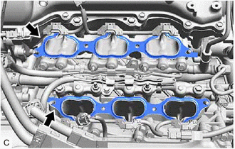
19. REMOVE INTAKE MANIFOLD
(a) Remove the 4 bolts, 4 nuts and intake manifold from the cylinder head sub-assembly.
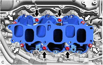
| | Bolt |
| | Nut |
20. REMOVE NO. 1 INTAKE MANIFOLD TO HEAD GASKET
| (a) Remove the 2 No. 1 intake manifold to head gaskets from each cylinder head sub-assembly. |
|
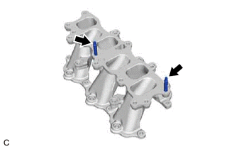
21. REMOVE STUD BOLT
HINT:
If a stud bolt is deformed or the threads are damaged, replace it.
| (a) Using an E8 "TORX" socket wrench, remove the 2 stud bolts from the intake manifold. |
|
READ NEXT:
 Installation
INSTALLATION PROCEDURE 1. INSTALL STUD BOLT HINT: If a stud bolt is deformed or the threads are damaged, replace it. (a) Using an E8 "TORX" socket wrench, install the 2 stud bolts to the intake man
Parts Location
PARTS LOCATION ILLUSTRATION *1 INTAKE AIR CONTROL VALVE (for ACIS) *2 ECM *3 ENGINE ROOM RELAY BLOCK AND JUNCTION BLOCK ASSEMBLY - EFI NO. 1 FUSE - -
SEE MORE:
Glass Position Initialization Incomplete (B2313)
DESCRIPTION The power window regulator motor assemblies are operated by the multiplex network master switch assembly, power window regulator switch assembly or rear power window regulator switch assemblies. The power window regulator motor assembly has motor, regulator and ECU functions. When the EC
On-vehicle Inspection
ON-VEHICLE INSPECTION PROCEDURE 1. CHECK FUEL PUMP WITH FILTER ASSEMBLY OPERATION AND INSPECT FOR FUEL LEAK (a) Check fuel pump operation. (1) Connect the Techstream to the DLC3. (2) Turn the engine switch on (IG). NOTICE: Do not start the engine. (3) Turn the Techstream on. (4) Enter the following
