Lexus ES: Installation
INSTALLATION
CAUTION / NOTICE / HINT
NOTICE:
This procedure includes the installation of small-head bolts. Refer to Small-Head Bolts of Basic Repair Hint to identify the small-head bolts.
Click here .gif)
PROCEDURE
1. INSTALL REAR ENGINE OIL SEAL
(a) Using height adjustment attachments and plate lift attachments, place the engine assembly on a flat level surface.
NOTICE:
- Using height adjustment attachments and plate lift attachments, keep the engine assembly level.
- To prevent the No. 2 oil pan sub-assembly from deforming, do not place any attachments under the No. 2 oil pan sub-assembly of the engine assembly.
- Using an engine sling device and engine lift, secure the engine assembly before servicing.
(b) Apply MP grease to the lip of a new rear engine oil seal.
NOTICE:
- Keep the lip free from foreign matter.
- Do not allow MP grease to contact the dust seal.
| (c) Using SST and a hammer, tap in the rear engine oil seal. SST: 09223-15030 SST: 09950-70010 09951-07150 Standard Depth: -0.9 to 1.1 mm (-0.0354 to 0.0433 in.) (From the edge of the cylinder block sub-assembly and stiffening crankcase assembly) NOTICE: Do not tap in the rear engine oil seal at an angle. |
|
.png)
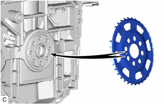
2. INSTALL NO. 1 CRANKSHAFT POSITION SENSOR PLATE
(a) Type A:
| (1) Install the No. 1 crankshaft position sensor plate. HINT: Align the pin hole of the No. 1 crankshaft position sensor plate with the pin of the crankshaft. |
|
(b) Type B:
| (1) Install the No. 1 crankshaft position sensor plate. HINT: Align the pin hole of the No. 1 crankshaft position sensor plate with the pin of the crankshaft. |
|
.png)
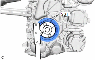
3. INSTALL FLYWHEEL SUB-ASSEMBLY
| (a) Using SST, hold the crankshaft pulley assembly. SST: 09213-54015 SST: 09330-00021 |
|
(b) Clean the bolts and bolt holes.
(c) Apply adhesive to 2 or 3 threads at the end of each of 8 new bolts.
Adhesive:
Toyota Genuine Adhesive 1324, Three Bond 1324 or equivalent
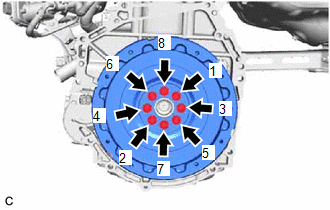
| (d) Install the flywheel sub-assembly with the 8 bolts. Uniformly tighten the 8 bolts in the sequence shown in the illustration. Torque: 150 N·m {1530 kgf·cm, 111 ft·lbf} NOTICE: Do not start the engine for at least 1 hour after installing the flywheel sub-assembly. |
|
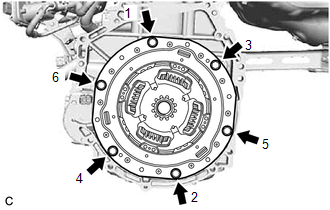
4. INSTALL TRANSMISSION INPUT DAMPER ASSEMBLY
| (a) Using SST, hold the crankshaft pulley assembly. SST: 09213-54015 SST: 09330-00021 |
|

| (b) Install the transmission input damper assembly to the flywheel sub-assembly with the 6 bolts. Uniformly tighten the 6 bolts in the order shown in the illustration. Torque: 30 N·m {306 kgf·cm, 22 ft·lbf} NOTICE:
|
|
5. INSTALL HYBRID VEHICLE TRANSAXLE ASSEMBLY
Click here
READ NEXT:
 Components
COMPONENTS ILLUSTRATION *A for EGR Valve Bracket Connection Type *B for Cylinder Head Cover Sub-assembly Connection Type *1 FUEL DELIVERY PIPE *2 FUEL INJECTOR SEAL *3 DIRECT
SEE MORE:
System Diagram
SYSTEM DIAGRAM Sender Receiver Signal Communication Method Radio Receiver Assembly Air Conditioning Amplifier Assembly Front wiper deicer switch signal CAN
Check Bus 4 Line for Short to GND
DESCRIPTION There may be a short circuit between one of the CAN bus lines and GND when there is no resistance between terminal 22 (CA2H) of the central gateway ECU (network gateway ECU) and terminal 4 (CG) of the DLC3, or terminal 7 (CA2L) of the central gateway ECU (network gateway ECU) and termina
