Lexus ES: Removal
REMOVAL
CAUTION / NOTICE / HINT
The necessary procedures (adjustment, calibration, initialization or registration) that must be performed after parts are removed and installed, or replaced during fuel sender gauge assembly removal/installation are shown below.
Necessary Procedures After Parts Removed/Installed/Replaced| Replaced Part or Performed Procedure | Necessary Procedure | Effect/Inoperative Function when Necessary Procedure not Performed | Link |
|---|---|---|---|
|
*: When performing learning using the Techstream.
Click here | |||
| Battery terminal is disconnected/reconnected | Perform steering sensor zero point calibration | Lane Control System (for Gasoline Model) | |
| Pre-collision System (for Gasoline Model) | |||
| Parking Support Brake System (for Gasoline Model)* | |||
| Lighting System (for Gasoline Model) | |||
| Memorize steering angle neutral point | Parking Assist Monitor System (for Gasoline Model) | | |
| Panoramic View Monitor System (for Gasoline Model) | | ||
| Initialize power trunk lid system | Power Trunk Lid System (for Gasoline Model) | | |
CAUTION:
-
Never perform work on fuel system components near any possible ignition sources.
.png)
- Vaporized fuel could ignite, resulting in a serious accident.
-
Do not perform work on fuel system components without first disconnecting the cable from the negative (-) battery terminal.
.png)
- Sparks could cause vaporized fuel to ignite, resulting in a serious accident.
NOTICE:
- After the engine switch is turned off, the radio receiver assembly records various types of memory and settings. As a result, after turning the engine switch off, make sure to wait at least 85 seconds before disconnecting the cable from the negative (-) battery terminal. (for Audio and Visual System)
- After the engine switch is turned off, the radio receiver assembly records various types of memory and settings. As a result, after turning the engine switch off, make sure to wait at least 85 seconds before disconnecting the cable from the negative (-) battery terminal. (for Navigation System)
PROCEDURE
1. REMOVE FUEL SUCTION TUBE WITH PUMP AND GAUGE ASSEMBLY
Click here .gif)
2. REMOVE FUEL SENDER GAUGE ASSEMBLY
| (a) Disconnect the fuel sender gauge assembly connector. |
|
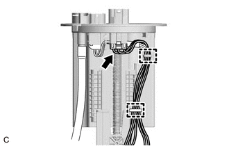
(b) Disengage the 2 clamps to disconnect the wire harness from the fuel suction plate sub-assembly.
NOTICE:
Do not damage the wire harness.
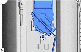
| (c) Disengage the claw to remove the fuel sender gauge assembly from the fuel sub-tank. NOTICE: Be careful not to bend the arm of the fuel sender gauge assembly. |
|
READ NEXT:
 Inspection
INSPECTION PROCEDURE 1. INSPECT FUEL SENDER GAUGE ASSEMBLY CAUTION: Perform the inspection in a well-ventilated area. Do not perform the inspection near an open flame. (a) Check that the float moves s
Installation
INSTALLATION PROCEDURE 1. INSTALL FUEL SENDER GAUGE ASSEMBLY (a) Engage the claw to install the fuel sender gauge assembly to the fuel sub-tank. NOTICE: Be careful not to bend the arm of the fuel send
SEE MORE:
Fuel Main Valve
ComponentsCOMPONENTS ILLUSTRATION *1 FUEL SUCTION TUBE WITH PUMP AND GAUGE ASSEMBLY *2 FUEL MAIN VALVE ASSEMBLY *3 FUEL PRESSURE REGULATOR HOLDER *4 O-RING ● Non-reusable part - - InstallationINSTALLATION PROCEDURE 1. INSTALL FUEL MAIN VALVE ASSEMBLY (a) Apply ga
Inspection
INSPECTION PROCEDURE 1. INSPECT REAR CENTER ULTRASONIC SENSOR (a) Measure the resistance according to the value(s) in the table below. Standard Resistance: Tester Connection Condition Specified Condition 4 (BI) - 6 (EI) Always 10 kΩ or higher 4 (BI) - 1 (BO) Always Below
